It's important to remember that a transformer's output power is (slightly) less than its input power. So if you want to use a transformer as the 2nd stage of a 3 stage power amplifier, it's important to have a 3rd stage whose input power requirements are very small; otherwise you need a big transformer and a first stage that's able to pump out lots of power.
The First Watt designs that have a transformer as the 2nd stage, accomplish this by using MOSFETs for their 3rd stage. Thanks to the high input impedance of MOSFETs, the power needed to drive them is small. So you can get away with a not-huge transformer and a not-ridiculous first stage.
The First Watt designs that have a transformer as the 2nd stage, accomplish this by using MOSFETs for their 3rd stage. Thanks to the high input impedance of MOSFETs, the power needed to drive them is small. So you can get away with a not-huge transformer and a not-ridiculous first stage.
Entirely possible. Drive the primary with a low Z source, maybe an emitter follower (or cathode follower). To be using global fb, you may need to set the turns ratio high, say 20dB to tolerate 18dB of fb, but be aware that the impedance transformation is n squared, so 10,000 times higher the Zin. Furthermore, there is heavy phase shift, so the stability issue is tricky to keep it calm. But it's doable; plenty of interstage transformers used in tube amps. Problem is to build a very good transformer with good FR you need to spend $$.
HD
HD
The concept is not new, done both commercially and by amateurs. Here is a beautiful example: two diamond buffers and a SUT sandwiched between them.
Low power, no overall nfb, high demands for parts quality, extreme demands towards the SUT, a general concept that annoys engineers. What's not to like?")
Low power, no overall nfb, high demands for parts quality, extreme demands towards the SUT, a general concept that annoys engineers. What's not to like?
Attachments
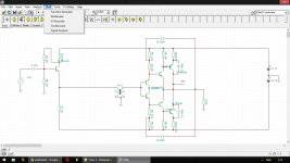
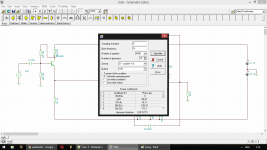
analog_sa, very ugly schematic is this
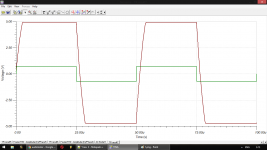
This is what I simulated. The squares are 20khz.
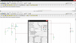
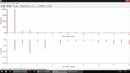
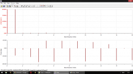
THD is measured at half power.
As follows:
0.018% 1khz
0.080% 20khz
This is what I simulated. The squares are 20khz.
THD is measured at half power.
As follows:
0.018% 1khz
0.080% 20khz
Attachments
Last edited:
Dunno about your cfp fetish Or that emitter follower.
Anyway, results don't appear bad to me at all. In real life the squarewave will look significantly worse as well, but so what?
Dartzeel uses a similar output stage and is considered to be among the best sounding amps ever. The "Ulyanov" amp i posted, built properly should sound even better.
Or that emitter follower. Anyway, results don't appear bad to me at all. In real life the squarewave will look significantly worse as well, but so what?
Dartzeel uses a similar output stage and is considered to be among the best sounding amps ever. The "Ulyanov" amp i posted, built properly should sound even better.
- Status
- This old topic is closed. If you want to reopen this topic, contact a moderator using the "Report Post" button.
- Home
- Amplifiers
- Solid State
- Transformer for a VAS stage ?