Hey all,
Glad to be aboard DIYaudio!
My first post is to get any advice I can on modifying the P50 (I'm unsure if I have MKI or II) for mains operation 115-120V, instead of UK 220V.
I have some experience in electronics, but have never worked a 220V device. First thing I did when I opened the enclosure was to probe the monster caps, and discharge with a 10 megahom resistor, just in case.
I've located the service manual on hifiengine.
First thing first. Do I even need to do any modifications to run this on US 120V mains? The service manual makes this ambiguous statement:
This explicitly states that mains is "preset within the unit" to 110/120 OR 220/240. Does this mean main power in is configured in such a way, like with a switching power supply, that all I need to do is slice the PSU cord and put on a north american edison three prong?
Then there is the also confusing (to me) statement about the outputs, not inputs. I don't know what these outlets are for (external pre-amps maybe?), but I'm unsure if the following few pages of instructions on how to perform a "mains changeover" is to alter the voltage of the outlets, or alter the voltage of the input transformer.
If a new transformer is required, does anyone have any suggestions for which transformer I need? I think I'll be able to handle the wiring.
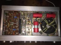
Attached are a few pics from inside.
Thanks!
Glad to be aboard DIYaudio!
My first post is to get any advice I can on modifying the P50 (I'm unsure if I have MKI or II) for mains operation 115-120V, instead of UK 220V.
I have some experience in electronics, but have never worked a 220V device. First thing I did when I opened the enclosure was to probe the monster caps, and discharge with a 10 megahom resistor, just in case.
I've located the service manual on hifiengine.
First thing first. Do I even need to do any modifications to run this on US 120V mains? The service manual makes this ambiguous statement:
An externally hosted image should be here but it was not working when we last tested it.
This explicitly states that mains is "preset within the unit" to 110/120 OR 220/240. Does this mean main power in is configured in such a way, like with a switching power supply, that all I need to do is slice the PSU cord and put on a north american edison three prong?
Then there is the also confusing (to me) statement about the outputs, not inputs. I don't know what these outlets are for (external pre-amps maybe?), but I'm unsure if the following few pages of instructions on how to perform a "mains changeover" is to alter the voltage of the outlets, or alter the voltage of the input transformer.
An externally hosted image should be here but it was not working when we last tested it.
An externally hosted image should be here but it was not working when we last tested it.
An externally hosted image should be here but it was not working when we last tested it.
If a new transformer is required, does anyone have any suggestions for which transformer I need? I think I'll be able to handle the wiring.
Attached are a few pics from inside.
Thanks!
Attachments


It looks from 2.3 in the manual that you have a transformer with two primary windings, which are wired differently depending on which input voltage you have. The table shows which coloured wires should be wired to where. First thing to check would be do your wires correlate with the 220 or 240V in that manual page.
But if you are unsure about this, then perhaps giving it to a qualified technician is the best option.
Tony.
But if you are unsure about this, then perhaps giving it to a qualified technician is the best option.
Tony.
> Do I even need to do any modifications to run this on US 120V mains?
Yes.
> mains is "preset within the unit" to 110/120 OR 220/240
UK market are preset to 240V. US market are preset to 120V. The "OR" is at the factory, not in your hands.
> I've located the service manual on hifiengine.
Something broke in that link. However if you have the manual, did you see section 2.3 (page 9 in the PDF, 14 on the page)?? Take apart, re-wire.
Attachments
It looks from 2.3 in the manual that you have a transformer with two primary windings, which are wired differently depending on which input voltage you have.
Tony.
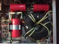
Ah! OK. This makes much, much more sense now. And would explain why this is among the largest non-industrial transformers I've seen in a SS consumer device.
So all I'm doing is re-wiring to the 110/120V primary winding vs. the 220/240 primary it was factory wired to, for UK mains, and the secondary is wound and configured in such a way that the operating voltage delivered to the circuit remains the same.
I got this for $20. It's a bit beat up aesthetically, and I located one blown fuse in the left or right (can't remember) channel (there are three fuses, one mains protection fuse, and then two for each stereo channel). The spare fuses are on their way and I hope replacement will solve whatever is wrong. Then again fuses blow for a reason and I fear having to replace those monster red capacitors, or more.
Basically you have two 110V primary windings. You connect them in series for 220v or in parallel for 110V. Making sure you get the polarity of the windings correct. You also need to double the value of the mains fuse for 110V operation. As for as the blown channel fuse, try putting a 47 ohm resistor in lieu of the fuse and power it up without a load. Then measure the offset voltage at the speaker terminal. If the resistor doesn't go up in smoke and the offset voltage is a few millivolts or so, fit the fuse and connect a speaker for a test. Resistors are cheaper than semiconductors.
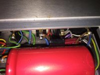
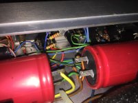
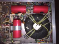
I can see the Brown (Live) and Blue (Neutral) wires running from top right corner under the red cap to reach the group of wires into the transformer.Hey all,
Glad to be aboard DIYaudio!
My first post is to get any advice I can on modifying the P50 (I'm unsure if I have MKI or II) for mains operation 115-120V, instead of UK 220V.
I have some experience in electronics, but have never worked a 220V device. First thing I did when I opened the enclosure was to probe the monster caps, and discharge with a 10 megahom resistor, just in case.
I've located the service manual on hifiengine.
First thing first. Do I even need to do any modifications to run this on US 120V mains? The service manual makes this ambiguous statement:
An externally hosted image should be here but it was not working when we last tested it.
This explicitly states that mains is "preset within the unit" to 110/120 OR 220/240. Does this mean main power in is configured in such a way, like with a switching power supply, that all I need to do is slice the PSU cord and put on a north american edison three prong?
Then there is the also confusing (to me) statement about the outputs, not inputs. I don't know what these outlets are for (external pre-amps maybe?), but I'm unsure if the following few pages of instructions on how to perform a "mains changeover" is to alter the voltage of the outlets, or alter the voltage of the input transformer.
An externally hosted image should be here but it was not working when we last tested it.
An externally hosted image should be here but it was not working when we last tested it.
An externally hosted image should be here but it was not working when we last tested it.
If a new transformer is required, does anyone have any suggestions for which transformer I need? I think I'll be able to handle the wiring.
Attached are a few pics from inside.
Thanks!
Can you look at that group of wires and tell us what each colour is and how many there are?
We need that information to help you determine if you have a dual primary transformer, or a single primary transformer.
A single primary transformer with a label clearly stating 240V can ONLY be used on a 240Vac mains supply. It will work adequately on the 220Vac EU harmonised supply.
It will not work properly on the 110/120Vac North America mains supply.
It would help me if you could attach the missing pics/info.
Last edited:
From the pic in this post it looks like they used four differently wired transformers to suit different regions around the world.> Do I even need to do any modifications to run this on US 120V mains?
Yes.
> mains is "preset within the unit" to 110/120 OR 220/240
UK market are preset to 240V. US market are preset to 120V. The "OR" is at the factory, not in your hands.
> I've located the service manual on hifiengine.
Something broke in that link. However if you have the manual, did you see section 2.3 (page 9 in the PDF, 14 on the page)?? Take apart, re-wire.
First interpretation:
110Vac dual primary on the left. This can be re-wired to suit 220Vac (EU and others).
120Vac dual primary 2nd from left. This can be re-wired to suit 240Vac (UK).
220Vac single primary 3rd from left. This cannot be re-wired to suit any other voltage.
240Vac single primary on the right. This cannot be rewired to suit any other voltage. But it will work adequately on the 220Vac used in Europe.
Second interpretation:
The transformer has a universal winding arrangement with dual windings, each winding having 0Vac, 10Vac and 120Vac tappings.
This adds up to 6 wires to feed in mains power.
For 110Vac are Br, Y, R and G with O and Bl left open circuit, but insulated.
For 120Vac are Br, Y, O and Bl with R & G left open circuit, but insulated.
For 220Vac are Br, G to mains and series connected at R & Y with O & Bl left open circuit, but insulated.
For 240Vac are Br, Bl to mains and series connected at O & Y, with R & G left open, but insulated. If it is wired for 240Vac as shown on the label you should be able to see the series connection of O & Y and see the open but insulated R & G.
If the second interpretation is correct then:
first winding
Br is 120Vac tapping
R is 10vac tapping
O is 0Vac tapping
second winding
Y is 120vac tapping
G is 10Vac tapping
Bl is 0Vac tapping
This is the first thing you need to check using a continuity meter. You MUST identify which tappings are on which windings.
And use a Mains Bulb Tester to power ON to prevent damage to the transformer if you get any of the wires mixed up.
Last edited:
Apologies for all those broken links.
The broken link to the manual is I believe caused by hifiengine bouncing visitors who are not signed in - I thought maybe it was just a passwall and a permalink to the PDF beyond, but no cigar.
Here is the link to the P50 page: https://www.hifiengine.com/manual_library/cambridge-audio/p50.shtml I would attach here, but don't want to anger Hifiengine - I assume someone gets paid this way.
The confusion started for me on page 12:
"SUPPLY
Mains power supply, preset within unit
to accept 110/120V or 220/240V."
Interesting clause. I interpreted it to mean there might be a switching up/downconverter PSU (which I think if read literally, it does say that, and could have been clarified by adding "must be" after "mains power supply"), but then opened mine up and took one look at that beast of a torroidal, and the date this was manufactured, and said waaaaaiiiiit a minute.
Then, the information for how to go about wiring (or "preset") within the unit is detail on page 14, sec 2.3, as helpfully pointed out by PRR, "Mains Voltage Changeover"
I'm attaching some additional pictures I took yesterday in addition to those I posted earlier. I will take additional pics as necessary when I get back into the lab/office (I am not an engineer, but work with them and must understand some electrical concepts for the work I do)
Once I re-wire and plug in to 120V mains for testing, I go through a hammond isolation transformer for safety.
Very helpful community here, appreciated!
AFRF
Attachments
- Status
- This old topic is closed. If you want to reopen this topic, contact a moderator using the "Report Post" button.
- Home
- Amplifiers
- Solid State
- Assist with Cambridge P50 Mains Changeover