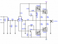
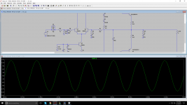
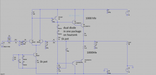
Hi, I own some TIP147-142 's and this is the schematic I build some time ago but it had some noise-hiss that i didn't like.
Today I was messing around in LTSpice and "modified " the schematic ( used NPN Long tail pair, I heard it's better than PNP and i have 20x 2n5551 without complementary so I can use them )
and in the end it looks very simmilar to mr Rod elliot's p3a.
Would it be worth making it ? at least for fun / to see how it performs, take a look.
- Cheers, Bruno.
Attachments
") You learn much by building stuff like this.
You learn much by building stuff like this.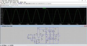
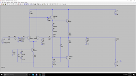
What is the " optimum / recommanded " current across the LTP ?
In simulations almost 1mA per transistor works good , 5mV dc offset ( I dont think in reality i can obtain that low ?! )
Also the VAS at 3.6 mA.
The 240 ohm resistor ( R2 ) is a pot in the actual PCB , Should i connect the multimeter on the output and just adjust for lowest DC offset possible and that would be ? or I need to connect on the LTP emmiter's and measure mA ?
Thanks.
Your VAS current is a major limiting factor with your design, particularly with that 100pf cap slugging the stage. Reducing the 4k7's to say 1k5 would give you around 6ma (and you could go a little higher still with those low supply voltages.
Also you will find in practice that the amp is much better behaved if you reduce the feedback factor by reducing the 1k.
The LTP currents are fine for what it is. The 240 ohm can be tweaked for minimum offset and you measure this directly across the speaker output.
Another possible issue is bias stability... it really needs a vbe multiplier in place of those two diodes.
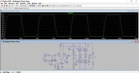
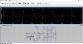
This shows the squarewave response at 25khz with 6ma VAS current and the 1k now at 220 ohm. Second picture is the original values.
Also you will find in practice that the amp is much better behaved if you reduce the feedback factor by reducing the 1k.
The LTP currents are fine for what it is. The 240 ohm can be tweaked for minimum offset and you measure this directly across the speaker output.
Another possible issue is bias stability... it really needs a vbe multiplier in place of those two diodes.
This shows the squarewave response at 25khz with 6ma VAS current and the 1k now at 220 ohm. Second picture is the original values.
Attachments
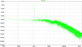
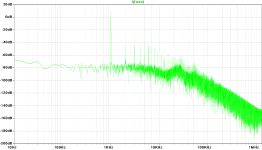
First time i made the schematic in LTspice there were 3.3k resistors but the DC offset was to high and the quiss current too i think ( can't remember why i increased them )
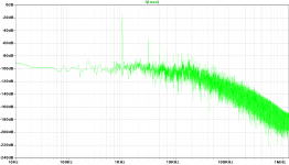
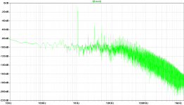
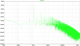
Here are some FFT's with the 4.7k resistors ( in square wave they looked weird - the ones you posted , but why should i care about square wave if the signal is sine wave ? )
It was a bad connection ! now it works fine even with 1.5k ,
Soo , I use 1.5k instead of 4.7k ? for the was to be 6mA or so.
Here are some FFT's with the 4.7k resistors ( in square wave they looked weird - the ones you posted , but why should i care about square wave if the signal is sine wave ? )
It was a bad connection ! now it works fine even with 1.5k ,
Soo , I use 1.5k instead of 4.7k ? for the was to be 6mA or so.
Attachments
Last edited:
Posts 19 and 20 here will explain how to get a percentage distortion figure for any given test frequency:
http://www.diyaudio.com/forums/soft...ltspice-iv-beginner-advanced.html#post4031841
Post #31 shows how to set up a squarewave:
http://www.diyaudio.com/forums/soft...ltspice-iv-beginner-advanced.html#post4032832
The VAS current depends totally on the particular design and what you require of it. Two of the most important factors are that there must be sufficient current available to both charge and discharge the 100pf cap at higher frequencies and also there must be sufficient current available to drive the output stage fully.
The diff pair still could be seriously out of balance, and the currents may be closer with an offset at the output. Try adjusting the collector load resistor on the input tranny - trim that till the input pair currents are the same. If there is a serious offset when you do that the input pair isn't matched well enough.
You also may have significant crossover distortion, and that may be "better" with some output offset. That would keep one output tranny in class A until you go past the zero point and it's forced to switch to the other side of the comp pair.
You also may have significant crossover distortion, and that may be "better" with some output offset. That would keep one output tranny in class A until you go past the zero point and it's forced to switch to the other side of the comp pair.
Please show a complete schematic of the real thing, there never was a DC offset adjustment in your sims. These don't generally have the kind of range to compensate for a whopping 20 V either. This amplifier should have a DC gain of unity. Feedback not connected or something?
If built as simulated, there's 2x diode + 1x 100R * 6 mA worth of bias voltage for 4 B-E voltage drops... definitely underbiased. A Vbe multiplier with the transistor (e.g. BD139) mounted on the common heatsink is recommended.
+1You also may have significant crossover distortion, and that may be "better" with some output offset. That would keep one output tranny in class A until you go past the zero point and it's forced to switch to the other side of the comp pair.
If built as simulated, there's 2x diode + 1x 100R * 6 mA worth of bias voltage for 4 B-E voltage drops... definitely underbiased. A Vbe multiplier with the transistor (e.g. BD139) mounted on the common heatsink is recommended.
The output transistors of the discrete Darlingtons could really do with some B-E resistors to help speed things up and also minimize leakage. 100 or 220 ohm should be good.
If you set the offset to near zero and also have at least a few milliamps flowing in the outputs and it still sounds terrible then you need to look with a scope at what is going on.
If you set the offset to near zero and also have at least a few milliamps flowing in the outputs and it still sounds terrible then you need to look with a scope at what is going on.
A scope is pretty much mandatory for any design work like this. It tells you so much.
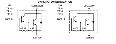
I wasn't sure what transistors you were using, the discrete Darlington in the diagram or the real TIP's. With no speaker attached you need to be seeing at least 2 to 3 millivolts DC across each 0.22 ohm. If you have no voltage across those resistors then you will hear distortion.
How have you built the amp ?
These designs can be amazingly critical on layout and grounding. I wonder if problems there are provoking instability.
- Status
- This old topic is closed. If you want to reopen this topic, contact a moderator using the "Report Post" button.
- Home
- Amplifiers
- Solid State
- Darlington Amp