Or you might just build a "good" circuit and stop wasting time trying to polish a turd.
Sometimes you don't want to create a complete "new house" - sometimes you want to recycle or repair "old stuff" too ...
If you want new designs have a look here.
Thanks!...
congrats on your successes!
...
You don't want to tap the mounting holes here, though.
I use this heatsink only for testing - the parts will be removed afterwards.
The TAA761A amp was just for fun if I could redo it from my mind more as 30 years later ...
The Edwin 40W based amplifier is still sitting here to be repaired/renewed. Change all lytics and remove/replace the old and noisy BC237B by BC550 and similar. Most circuits should work without major changes.
The amplifier section in this amp is one exception. I will add/change some parts as described above to bring "new light through old windows" (CD title from Chris Rea).
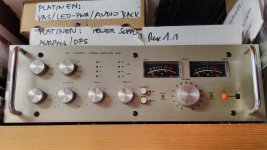
After restoration the amp will play a nostalgic role in my 80s party room together with an old cassette deck.
Attached the AS81 - or translated into my new naming convention - the "SA1981".
BR, Toni
Attachments
Prolly not, I would rather guess these weren't sealed very well and some absorbed moisture and went leaky over the years. Might be interesting to see what they say after a few hours in the oven (not overdoing the temperature of course, maybe 80-100°C). Of course that wouldn't help if it's a bonding problem or the silicon itself is degraded, but it's worth a shot and would seem like a fun exercise.Does anybody know the cheap "TP 2N3055" (on other side "Mexico") shown in background. The hFe measured for 10 pcs goes from 9 to 130. Maybe I have bought fakes 35 years ago?
"What's that in the oven, honey?" - "Oh, just a bunch of transistors..."
Wow, that's really lousy, especially for something that does not have to be unity gain compensated. The (lousy and confusing) datasheet seems to imply that unity gain stability is reached at 18 pF (with about a 10 MHz GBW), so 33 still strikes me as quite high. You may want to play with lower values if you have some floating around, and reduce external GBW with another cap (or R-C, or even something 2nd-order) from output to inverting input if the output stage requires it.TMC compensation works as simulated.
Slewrate of the TAA761 with gain 19 is awful bad 0.4V/µs rising edge and 3V/µs falling edge.
This chip seems to have a rather disadvantageous ratio of GBW and slew rate. At 33 pF, your GBW should already be at around 3 MHz, but slew rate is slower than on a 4558 or µA741. Typical undegenerated bipolar inputs tend to be at around 0.5 V/µs per 1 MHz of GBW when unity gain stable - someone actually showed that there is a direct correlation back in the '70s, maybe I can find the article.
They almost always are when feedback network resistor values are halfway low though.The SNR values where very good for that time (see measurement above)
Hmm, some distortion cancellation going on there?THD1k 1W@4R 0.11%
THD1k 25W@4R 0.04%
Last edited:
...
Hmm, some distortion cancellation going on there?
No - the crossover region is the problem when we leave class A (BD139/BD140; 30mA) and the 2N3055 start to work.
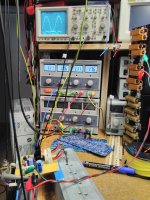
Hard to get stability near full power. The circuit seems to be stable using only a 10 - 15p miller, but when it comes to full power the output stage starts some oscillation. A base resistor (4.7R for 2N3055) helps but does not cure it completely.... The (lousy and confusing) datasheet seems to imply that unity gain stability is reached at 18 pF (with about a 10 MHz GBW), so 33 still strikes me as quite high. You may want to play with lower values if you have some floating around, and reduce external GBW with another cap (or R-C, or even something 2nd-order) from output to inverting input if the output stage requires it.
...
Using 22pF/220p/2.2k TMC and a 330R/10pF parallel to feedback resistor cures the oscillation, betters the slew rate to about 1VµS/6Vµs.
Very good THD figures.
More breadboard testing needed.
Some circuits are using TAA761A and BD675/BD676 with compensation 10pF but also with 33pF.
BR, Toni
TMC compensation can't be used here with success in getting better slew rates.
TPC compensation using 39pF/68pF/2.2k and a 330R/10pF parallel to feedback resistor looks promising.
Now we have better slew rates and can do 20kHz full power with - surprise surprise - 0.076% THD+N @4R
Picture shows 20kHz@25W@4R full power
TPC compensation using 39pF/68pF/2.2k and a 330R/10pF parallel to feedback resistor looks promising.
Now we have better slew rates and can do 20kHz full power with - surprise surprise - 0.076% THD+N @4R
- THD1k+N @25W@4R: 0.0062%
- THD10k+N @25W@4R: 0.019%
- THD20k+N @25W@4R: 0.076%
Picture shows 20kHz@25W@4R full power
Attachments
Last edited:
Vintage series: TAA761A opamp - 2N3055 quasi compl. amplifier - 25W@4R
... replacing the base resistors 4.7R by ferrit beads cured the shoot through at higher full power frequencies.
THD+N at low frequencies (< 100) was relatively high (0.1% at 20Hz@25W@4R). Replaced the 2200µF output capacitor by a 4700µF and we get THD+N well below 0.1%.
Slew rate is still asymmetric and low but enough for 20kHz full power: ~ 3Vµs rising / 9Vµs falling edge.
- Status
- This old topic is closed. If you want to reopen this topic, contact a moderator using the "Report Post" button.
- Home
- Amplifiers
- Solid State
- Discrete TAA761A opamp - 2N3055 quasi compl. amplifier - 50W@4R

