In the original the input is transformer coupled.
http://perso.wanadoo.fr/jm.plantefeve/Gibouin.html
hope you can read French. Has anyone built this?
Regards,
Jam
mwh-eng the answer is no.
http://perso.wanadoo.fr/jm.plantefeve/Gibouin.html
hope you can read French. Has anyone built this?
Regards,
Jam
mwh-eng the answer is no.
Hi Jam.
My favourite audio circuits are derivatives of the JLH-69/96 class-A that have been upscaled and have paralleled bipolar output transistors to provide a more powerful output. But I am always on the lookout for any topology that might be better.
Your entry is balanced and simple, but is likely to introduce a propagation delay which will affect the rising edges of transients, and impair high audio frequency damping. Though good I could 'imagine' it sounding less transparent than the very low propagation delay 'JLH class-A's do on complex passages, due to the way in which there is a potential to distort leading edge reproduction.
Is there an exponential start-up delay to the first couple of microseconds of say a 10kHz sinewave which varies with load impedance. Maybe fitting separate 220uF caps across each biasing pre-set will much improve both the transient and the NFB loudspeaker system damping responses by directly coupling the low impedance NFB divider to the input sources.
Hi Subwo1,
I have similar reservations about the input delay that might arise with your 62k series input resistors; I have not come across such high values before with a bipolar input. If they are included for reasons of high frequency stability, then they must equally degrade loudspeaker back emf control at higher audio frequencies because Q1 and Q6 do not provide a low impedance for Q2 and Q5 NFB reference.
I suspect that the C-bc currents of Q7 and Q3 will begin to have a delaying effect upon Q1 and Q6 responses in much the same way as when Miller C.dom capacitors are fitted to differential pairs that have emitter resistors.
Q1 - Q2 and Q6 - Q5 currents might be balanced at dc, but they could become phase shifted at higher audio frequencies, and especially on leading edges.
I note that your circuit is well balanced, and that the output devices are driven both into and out of conduction with low series gate resistance which is good for high frequencies.
I also wonder about L1 and R22, and whether it is intended to be the loudspeaker, or a series output choke network. Individual loudspeaker driver units might have series inductance, but when used in composite loudspeaker systems their rising impedance characteristic is normally compensated for by series capacitance and resistance; this approximates a resistor load.
Guys. I am not wanting to offend anyone here, or appear to be big headed. I haven't heard your designs nor simulated them. But I have heard and simulated amplifier circuits, and thus become aware of many short-comings as a result.
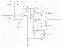
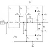
Well, this isn't exactly a totally solid state topology & the SOA, PS, dc offset adjust, paralleled output MOSFETs and startup circuitry have been omitted, but it's a representation of the HT dc coupled hybrid circuit I'm working on. Only one voltage gain stage in the amp, yet it should be capable of <1% distortion up to near clipping and possibly 100khz closed loop bandwidth with 26db of gain & only about 6db of AC loop feedback, so unconditional stability should be possible to achieve, even without an output choke. This is planned to be one of six channels for my HT amp project with each one good for 150WRMS into 8 ohms.
Attachments
My favourite design is like this. Input stage only consist of single differential, it gives more accurate sound for me, because it is only 2 transistors comparing input and FB, cannot be any "blur" or "slight double work mismatch" compared to full complementary differential (where N ch and P ch differential does the same job together)
The VAS is push-pull type, having more gain, harmonic canceling(learn from Mr. Pass and Mr. J. Curl).
How to connect single differential and push pull VAS? The idea is to use both legs of differential, the second differential leg is connected to current mirror, so it can drive lower VAS. Maybe this is where the design can be upgraded. Anyone has better idea than this current mirror?
I believe this lead us to rich harmonic sound, because JLH does not use differential front end (where differential cancels harmonics). I havent heard of JLH. Sound like tubes?
The VAS is push-pull type, having more gain, harmonic canceling(learn from Mr. Pass and Mr. J. Curl).
How to connect single differential and push pull VAS? The idea is to use both legs of differential, the second differential leg is connected to current mirror, so it can drive lower VAS. Maybe this is where the design can be upgraded. Anyone has better idea than this current mirror?
My favourite audio circuits are derivatives of the JLH-69/96 class-A that have been upscaled and have paralleled bipolar output transistors to provide a more powerful output
I believe this lead us to rich harmonic sound, because JLH does not use differential front end (where differential cancels harmonics). I havent heard of JLH. Sound like tubes?
Attachments
lumanauw said:How to connect single differential and push pull VAS? The idea is to use both legs of differential, the second differential leg is connected to current mirror, so it can drive lower VAS.
that's smart, very smart.
On the flip side, it uses the same number of transistors as in a fully complementory design. Any advantage one over another?
lumanauw said:I havent heard of JLH. Sound like tubes?
no, it doesn't. and thank God for that,
")
I'd have to say that my favorites are relative to the P3A by Rod Elliot for PP class AB, and the Zen and varients by Nelson Pass, for class A.
I have built both topologies with excellent and pleasing results. They have an interesting elegance and simplicity and tend not to leave you in the dust with over-complication.
I have listened to and enjoyed more complicated designs of course, and built some, but if you're looking for simplicity, these are a couple of excellent ideas.
As an extension if you want to get a little more complex, I really enjoy the topology used in Douglas Self's Blameless design.
I have adapted ideas from R. Elliot and D. Self to make an amplifier of my own design which I like very much.
Later I plan to make some class A stuff in tubes and transistors.
I am very glad you asked, jam. First I would to mention that I am presently working on improvements on my circuit and am anxious to post the update. Some of the changes are based on recent diyaudio member suggestions.
I continue to evaluate the comments Graham offered. The 62k input resistors do delay the input, but I think that since they are before the feedback loop, they don't add any real distortion to the signal. They do in fact enhance stability since they permit the feedback more opportunity to "catch up" to the input.
Presently, a preliminary explanation of those input transistor collector resistors (VAS base pull-down resistors) is that they work in concert with the 62k input resistors and the cascode effect of the feedback transistors' connection to the VAS emitter resistors. I agree that further explanation will be good and forthcoming from me or knowledgeable diyaudioers. I invite comments, even if the consensus ultimately indicates that my idea is quite flawed.
- Status
- This old topic is closed. If you want to reopen this topic, contact a moderator using the "Report Post" button.
- Home
- Amplifiers
- Solid State
- Amplifier Topologies