well, I put Q116 and Q119 back, restore all jumpers/connections as it was before (r133/134 to output etc) and got the picture as it was in the beginning +97/+92v at Q113/115 collectors. Yuck, I am devastated =(((
The most frustrating is difficulty of q116/119 soldering/desoldering, as they are on quite big radiators also soldered into PCB and each iteration does some harm to PCB.
The most frustrating is difficulty of q116/119 soldering/desoldering, as they are on quite big radiators also soldered into PCB and each iteration does some harm to PCB.
It looks like Q112 is not the only one that's been damaged.
I would check / replace Q116, Q117, Q118 as well.
You still test without powering on the output stage, connecting NFB to the middle point between R132, R178 or R134, R133 for this test.
the most mystic thing is that "old" Q112 tested and measured good with "transistor tester" and usual multimeter in Hfe mode. Same as Q116/119 - for sure I have tested them after desoldering. It looks like some mechanical problem on the PCB, possibly loose contact or cracked solder joint... will test 117-118 for sure...
Now I decided to try getting all jumpers back as in condition when it start working - however - without desoldering Q116 and Q119. So I removed jumpers from R133/134 and R132/178 to output and put back c111 shorting with connecting it to second drain of the input FET via 5.6k. And got the thing working, with zeroes at Q113/115 collectors, stable zero at c11 jumper adjustable with rt101. Also tested Q117/118 right on PCB - apparently full testing was not possible but they are definitely not shortened. Next move?
OK, makes sense.
My idea for the next move - leave one side of 5.6k at the right FET's input (it's gate, not drain), the other side of 5.6k - disconnect from C111 (also remove the wire, shorting it), and connect to the middle point between R134, R133. Now pre-drivers and drivers are also in the game, NFB signal is taken from the driver's output. If you see zero offset at that middle point - the drivers work fine.
My idea for the next move - leave one side of 5.6k at the right FET's input (it's gate, not drain), the other side of 5.6k - disconnect from C111 (also remove the wire, shorting it), and connect to the middle point between R134, R133. Now pre-drivers and drivers are also in the game, NFB signal is taken from the driver's output. If you see zero offset at that middle point - the drivers work fine.
yes, it works. I was able to set full zero at resistors cross-point, however in this case the readings at q113/115 collectors are 3.7/-2.8. If I adjust rt101 for equal readings, then I have -0.6 at the output. Nevertheless, I think this is OK for now. Now I am looking to check voltages on output FETs gates (+/- 1.8) and if they are, I will put couple of "test" fets to output, just to understand if its possible to assemble the full thing and test it without frying the parts.
Gents,
the amp is working after the output fets were restored and power rails soldered back to PCB. However, remaining small issue is still irritating - if the voltages at Q113/Q115 collectors are +/-3.5V then we have -0.6V DC at the output. And if output voltage is adjusted to 0, those voltages have readings of +4V/-2.5V. Not sure, but I assume that even if there's a difference at rails, that should not have such influence.
the amp is working after the output fets were restored and power rails soldered back to PCB. However, remaining small issue is still irritating - if the voltages at Q113/Q115 collectors are +/-3.5V then we have -0.6V DC at the output. And if output voltage is adjusted to 0, those voltages have readings of +4V/-2.5V. Not sure, but I assume that even if there's a difference at rails, that should not have such influence.
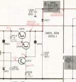
by the way, any chance to substitute d403/d404 ? it is current limiting diodes of unknown specs, originals are obsolete. I understand that some resistor will suit, but how to calculate its nominal?
Little math and model number (10YG1.1) gives as a clue...these should be 1.1mA CLD like Microsemi 1N5298. D403 could be replaced with the simple 10k resistor, but I could only guess about a resistor value instead of D404 as your uploaded image does not show referent voltages..If D401 is 5V1 zener, then D404 could be replaced with a 68k resistor.
Btw, could you please upload service manual you have as it seems different from the one available at hifiengine.com.
- Status
- This old topic is closed. If you want to reopen this topic, contact a moderator using the "Report Post" button.
- Home
- Amplifiers
- Solid State
- sony ta-n9 biasing
