Did you add 5.6K resistor? This is important.
sure.
OK, the circuit has to balance itself in this case. If you see almost the rail voltage at the output - something is not right with IPS / VAS stages. Must be close to zero.
See the voltage drop across R124, then voltage across D104. Is there any?
Then see the voltage over R121. Then the drop over R103, R105.
Then we'll see where to go next )
See the voltage drop across R124, then voltage across D104. Is there any?
Then see the voltage over R121. Then the drop over R103, R105.
Then we'll see where to go next )
OK, the circuit has to balance itself in this case. If you see almost the rail voltage at the output - something is not right with IPS / VAS stages. Must be close to zero.
See the voltage drop across R124, then voltage across D104. Is there any?
Then see the voltage over R121. Then the drop over R103, R105.
Then we'll see where to go next )
voltage drops:
d104=5.5v
r124=5.1v
r121=21v
r103=0.6v
r106=0.6v
The last one is R105, right?
OK.
Current through R121 is way too high (21V / 0.82K = 25.6mA
The question now - where does it go?
Can you disconnect D107, D108 as well? That's the only idea I have with regards to "where it goes"".
After you disconnect them - see if the VAS output voltage comes close to zero.
If it's still 97V or so at the output, next things to check are Q112, Q113.
The last one is R105, right?
OK.
Current through R121 is way too high (21V / 0.82K = 25.6mA
The question now - where does it go?
Can you disconnect D107, D108 as well? That's the only idea I have with regards to "where it goes"".
After you disconnect them - see if the VAS output voltage comes close to zero.
If it's still 97V or so at the output, next things to check are Q112, Q113.
Many thanks. Will check on Monday, when back from vacations )
sure! all rails are fine. The most questioning thing for me is Q115, which has -105V at emitter, -100V at base and +92V at collector. Checked it twice with removing, BJT is OK.
voltage drops:
d104=5.5v
r124=5.1v
r121=21v
r103=0.6v
r106=0.6v
Did you see these very different statements? Thus, I don't suspect Q115 any more.
I'm very curious on the outcome and will stay tuned!
Best regards!

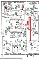
That's fine, the question is - why the circuit is so unbalanced (assuming 5.6k resistor is in place, as shown on the schematic attached).
Can you please measure the voltages at the points, marked by the red numbers:
1 =
2 =
3 =
etc.
No need. Just changed Q112 for another and all works fine. Got zero at c111 shortened and voltage amplifier working, with output zero adjusted by RT101. Strangely previous Q112 also measures good... got replaced with a970.
- Status
- This old topic is closed. If you want to reopen this topic, contact a moderator using the "Report Post" button.
- Home
- Amplifiers
- Solid State
- sony ta-n9 biasing