2 days ago, i come to my relative house with my mom
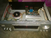
after some family conversation, i see her amplifier on the table
i ask her is this good or not
she answer me, this is almost doomed
so i take it down to my home for repair
you know, asian people habit always help their relatives and neighbors without payment
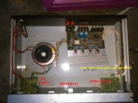
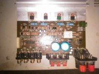
so after open this thing i found something weird...
this amplifier is a cheap china product but have toroid, something rare today in my country
after some test, i found this sound is not good
repairing its tone control testing with my amplifier and its good
but testing amplifier circuit, i can't say anything
so this is my plan...
i will change every transistor into good one
also with cheap transistor too but good ones
my idea is changing final transistor to TIP41 and TIP42, driver with c945 and a733
is it possible or not???
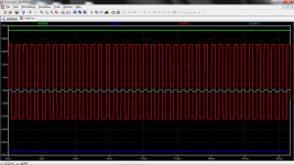
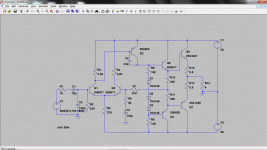
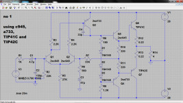
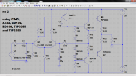
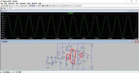
i put a result of LTSpice and schematic from LTSpice too
amplifier brand is Mikawa AV100
toroid is 80VA
regards
after some family conversation, i see her amplifier on the table
i ask her is this good or not
she answer me, this is almost doomed
so i take it down to my home for repair
you know, asian people habit always help their relatives and neighbors without payment
so after open this thing i found something weird...
this amplifier is a cheap china product but have toroid, something rare today in my country
after some test, i found this sound is not good
repairing its tone control testing with my amplifier and its good
but testing amplifier circuit, i can't say anything
so this is my plan...
i will change every transistor into good one
also with cheap transistor too but good ones
my idea is changing final transistor to TIP41 and TIP42, driver with c945 and a733
is it possible or not???
i put a result of LTSpice and schematic from LTSpice too
amplifier brand is Mikawa AV100
toroid is 80VA
regards
Attachments
While the transistors are out you can check the resistors to see if any are open circuit.
If you have an LCR meter check the capacitors as well.
have been checked transistors
they are almost doomed
need help for this one cause there is no one sell this type again near my home town
have been checked transistors
they are almost doomed
need help for this one cause there is no one sell this type again near my home town
Yes I know.
But while transistors are out check other discrete components.
Sometimes a faulty transistor can burn out resistors too.
Yes I know.
But while transistors are out check other discrete components.
Sometimes a faulty transistor can burn out resistors too.
all resistors are normal
also after first test and changing caps(same value) they are normal
Last edited:
Your schematic is misleading on the transistors used in the amplifier. From what I can see in the pictures, all of the to92 types are 2n5551 and 2n5401 and the outputs being 2sc2073/a940 pairs. The green one appears to be one that has been replaced previously. If the rail voltages are actually +/- 28 then it would be a sure thing those outputs would go bad before long. The tip41/42 pair should work ok as long as you use the A or better voltage rated ones, and if the 2n5551/5401's are not damaged I would leave them be.
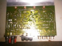
Yes there should be a connection from the junction of r10/11 to the junction of r12/13.
Well...
Like you said...
This thing not only make me confused...
Your schematic is misleading on the transistors used in the amplifier. From what I can see in the pictures, all of the to92 types are 2n5551 and 2n5401 and the outputs being 2sc2073/a940 pairs. The green one appears to be one that has been replaced previously. If the rail voltages are actually +/- 28 then it would be a sure thing those outputs would go bad before long. The tip41/42 pair should work ok as long as you use the A or better voltage rated ones, and if the 2n5551/5401's are not damaged I would leave them be.
That's one thing i have been thinking out last night...
On the PCB 5551 and 5401 but on the transistor 2N6520 and 2N6517
But there is no sign on the solder area those transistor have been repaired or changed before
But i am just found those A940 C2073 have been changed before
On the sim i use different final transistor cause i have no model for C2073 and A940
Never wondered on the sim results in the 1st picture? How does show do if you swap R7's right leg from rR0/R11 to R12/R13?
Best regards!
I will do it and soon reporting it to you if i swap a line from R10/R11 R7 to R12/R13
Never wondered on the sim results in the 1st picture? How does show do if you swap R7's right leg from rR0/R11 to R12/R13?
Best regards!
Have been swapped
Same result
I gave no idea why this manufacturer make thia model
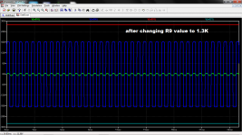
R9 is much to low at 1.3k, what was originally fitted ?
Reducing the value of R9 will tend to increase the output stage bias. As its not adjustable then that is probably not a good thing.
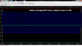
well i think it's the best idea but i will show you picture before and after changing R9 value from LTSpice
R9 original value is 12 K
i see positive side reach its peak first time than negative side
that's why i think the problem at R9
Attachments
Have you fixed the missing link that Kay Pirinha and Jerluwoo mentioned ?
i think it's not missing link...
i have been seen this pcb trace many times to find what's wrong about missing lines and it's not missing lines cause the manufacturer didn't make it as missing lines
the only thing i have found is 5pF capacitor(parallel with 33K R7) is missing but there is no sign(on solder area) it ever been exist there
i think it's not missing link...
It won't work properly without it because the feedback point is not sampling the output terminal. And if you move the feedback connection over to the output terminal then you would not need two separate 220 ohm resistors, a single resistor would be fitted.
Do some continuity checks and see where the feedback resistor goes.
- Status
- This old topic is closed. If you want to reopen this topic, contact a moderator using the "Report Post" button.
- Home
- Amplifiers
- Solid State
- help this mikawa amplifier, cheap but weird