Hmmm...
Hmm .. its just constructed with an NPN inputstage.
Not really common to do that but there should be no reason not to.
There are some diodes though that I really dont understand the purpose with using.
The ones at the output and the ones at the input ..
Anyone?
And I dont think the diode over the cap on the Feedback
is nessecary even if you use an electrolytic.
/Nysan "Hater of diodes"
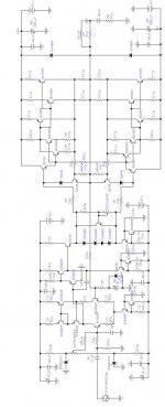
Diodes at the input
These are zener diodes and are used to create reference voltage either side of the trimmer so that the DC offset can be adjusted.
Diodes at the output
These are used as catch diodes to return any large back-EMF induced by the loudspeaker back into the supply rails rather than reverse-bias the output transistor and possibly damage it.
How do you figure that? With zero volts on the output, the voltage across the DC blocker would be zero volts too. How is there a right and a wrong way to zero volts?
Edit: However, on closer inspection I think the decoupling caps on the voltage rails to the output stage are the wrong way around.
Rune
Edit: However, on closer inspection I think the decoupling caps on the voltage rails to the output stage are the wrong way around.
Rune
As a standard practice the DC blocker looks the right way around to me. Normally the base current at the input transistor is enough to cause a small positive voltage at steady state. So this will get amplified x11, correctly polarising the nfb capacitor, then cancelled at the -ve differential input.
I'm not sure of the need for the Zener biasing to cancel the DC given that there is a DC blocker in the nfb loop. However given the zeners I think the nfb cap and the diode could be removed if the trimming is correct, provided you're not concerned about an OPS failure that could impress DC on the NFB that is.
Some times zeners on the input are used to provide input level protection, but the configuration is not the same as shown.
I think the 47uF DC-blocker should be connected with the opposite polarity. If we assume that the output is at zero and the DC bias for the basis is delivered through the feedback resistor, then this current will have to flow from output (zero) to the basis and result in a DC voltage at the basis just little below zero..... But in fact this voltage is small, so the cap will probably work without major issues not matter in which direction you connect it.
My general proposal is to use film caps, or use two electrolytic in anti seriell connection (double value each) and give some bias volts (5V....15V) with a high value resistor (1Mohm ....10Mohm) to the center tap of the series connection.
Bye
Markus
My general proposal is to use film caps, or use two electrolytic in anti seriell connection (double value each) and give some bias volts (5V....15V) with a high value resistor (1Mohm ....10Mohm) to the center tap of the series connection.
Bye
Markus
I was visiting old threads.
I will simulate this amplifiers and i will give you some results.
Maybe you already constructed it... tell me some.
When complicated this way, normally explode (Yes!.. thats i am seeing often)
But it is very interesting unit.... working, will be very good.
Carlos
I will simulate this amplifiers and i will give you some results.
Maybe you already constructed it... tell me some.
When complicated this way, normally explode (Yes!.. thats i am seeing often)
But it is very interesting unit.... working, will be very good.
Carlos

Re: Complicated amp electrolytics
well its me tooChrisW said:Is it just me? Or do those 2200 uF caps (smoothing caps) look the wrong way round to you?
Looks alot like a Randy Slone (Seal Electronics) design to me...
High Power Audio Amplifier Construction Manual...It looks like a concatination of two designs.
In that case - they sound fantastic! I built the design that he calls "OptiMOS" however, I ran it slightly higher - to make 200W. They are the nicest I've had in my system so far.
Gaz
High Power Audio Amplifier Construction Manual...It looks like a concatination of two designs.
In that case - they sound fantastic! I built the design that he calls "OptiMOS" however, I ran it slightly higher - to make 200W. They are the nicest I've had in my system so far.
Gaz
Nelson,
Was that a Kimmel-Gurke EMI seminar? I used to sponsor them here on Long Island. I sell for Tektronix, at least for the next 3 days, then on to another test and measurement manufacturer. If it was a Kimmel-Gurke seminar they also have a neet signal integrity seminar.
Was that a Kimmel-Gurke EMI seminar? I used to sponsor them here on Long Island. I sell for Tektronix, at least for the next 3 days, then on to another test and measurement manufacturer. If it was a Kimmel-Gurke seminar they also have a neet signal integrity seminar.
Konnichiwa,
This about as straightforward, broingly conventional and orthodox as it gets.
Loads of ring of two current sources and discrete darlington / follower buffered stages and the compund feedback pair output stage with large numbers of parallel transistors add up to a very high component count, but in the end it is a classic Amp, Long tailed Pair to Voltage Amp to Emitterfollower Output, basically the type of topology talked to death by D. Self and easly outperformed by superior designs that eshew the usual brainless design approach.
It arguably is more or less a consequent implementation of D.Self's "blameless" amplifier, but jut because the Amplifier is "blameless" it does not mean it is "good".
Look at some of the Jean Hiraga designed circuit and their descendants for something a little simpler and better performance.
Sayonara
HM666 said:What do you think abou this amp(schematic is aded as attachment)? Sory for image quality.
This about as straightforward, broingly conventional and orthodox as it gets.
Loads of ring of two current sources and discrete darlington / follower buffered stages and the compund feedback pair output stage with large numbers of parallel transistors add up to a very high component count, but in the end it is a classic Amp, Long tailed Pair to Voltage Amp to Emitterfollower Output, basically the type of topology talked to death by D. Self and easly outperformed by superior designs that eshew the usual brainless design approach.
It arguably is more or less a consequent implementation of D.Self's "blameless" amplifier, but jut because the Amplifier is "blameless" it does not mean it is "good".
Look at some of the Jean Hiraga designed circuit and their descendants for something a little simpler and better performance.
Sayonara
kilowattski said:Was that a Kimmel-Gurke EMI seminar?
It was put on by Compatible Electronics.
Hi Carlos,
One concern I have is with the protection circuitry. The design of the protection circuits makes the current limit constant regardless of output voltage. So if the designer makes the current limit small enough to prevent damage with a short circuit on the output, it will limit the amount of power that can be delivered into low-impedance loads (say, 4 Ohms) in an undesirable way. A better design makes the current limit depend on the output voltage, allowing the amp to deliver more current when its output is close to the voltage rail than when its output is near zero Volts This requires adding two resistors. They connect to the current limiting transistors (the ones with the diodes in their collectors). One resistor connects from the positive supply voltage to the base of the NPN current limiting transistor, and the other connects from the negative supply voltage to the base of the PNP current limiting transistor. This simple change allows the amp to put out more current the closer the output voltage is to the rail. It does require re-calculating the reisitor values though. I have an article on this I could send you if you wish. Just drop me an email if you'd like it.
One concern I have is with the protection circuitry. The design of the protection circuits makes the current limit constant regardless of output voltage. So if the designer makes the current limit small enough to prevent damage with a short circuit on the output, it will limit the amount of power that can be delivered into low-impedance loads (say, 4 Ohms) in an undesirable way. A better design makes the current limit depend on the output voltage, allowing the amp to deliver more current when its output is close to the voltage rail than when its output is near zero Volts This requires adding two resistors. They connect to the current limiting transistors (the ones with the diodes in their collectors). One resistor connects from the positive supply voltage to the base of the NPN current limiting transistor, and the other connects from the negative supply voltage to the base of the PNP current limiting transistor. This simple change allows the amp to put out more current the closer the output voltage is to the rail. It does require re-calculating the reisitor values though. I have an article on this I could send you if you wish. Just drop me an email if you'd like it.
- Status
- This old topic is closed. If you want to reopen this topic, contact a moderator using the "Report Post" button.
- Home
- Amplifiers
- Solid State
- Very complicated amp