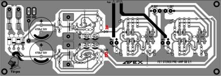
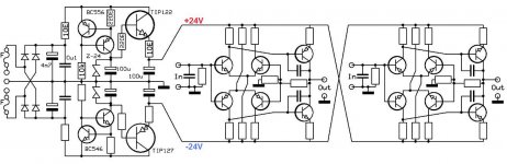
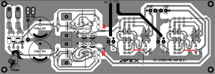
Ok so i have built the Apex SB3.1 Preamplifier. The problem is that the multimeter reads 10 Volts at point A and B. It should read 24 volts as indicated in the diagram.
Any idea why is this happening. I am using a 15-0-15 ( 1 Amp ) transformer. The transformer ground wire ( center tap ) is unused and the preamp is fed from the remaining 2 wires.
Any idea why is this happening. I am using a 15-0-15 ( 1 Amp ) transformer. The transformer ground wire ( center tap ) is unused and the preamp is fed from the remaining 2 wires.
Attachments

Ok so i have built the Apex SB3.1 Preamplifier. The problem is that the multimeter reads 10 Volts at point A and B. It should read 24 volts as indicated in the diagram.
Any idea why is this happening. I am using a 15-0-15 ( 1 Amp ) transformer. The transformer ground wire ( center tap ) is unused and the preamp is fed from the remaining 2 wires.
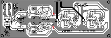
You must use transformer 24-0-24. You must connect center tap to gnd and you can use transformer 15-0-15 but you must relace 24v zeners with 15v zeners. This PCB have mistake... you can fix it use this pcb.
Attachments
You must use transformer 24-0-24. You must connect center tap to gnd and you can use transformer 15-0-15 but you must relace 24v zeners with 15v zeners. This PCB have mistake... you can fix it use this pcb.
Thanks for the reply. Apart from using a 24-0-24 transformer and connecting center tap to ground. Is there any other change that i need to do in the circuit ?
Yes - see the two traces at the far right? Observe how that area differs between the two layouts.
I would also cut the integrated ground loop even if it looks rather harmless.
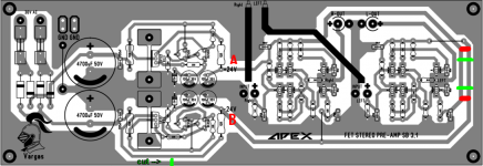
Green: cuts
Red: connections
Thanks. Any reason why to cut the ground loop? it really looks harmless.
Thanks. Any reason why to cut the ground loop? it really looks harmless.
My thoughts also, as there ist virtually nothing happening in the outer copper area. It's just grounded and perhaps acts as a shield. Signal ground is in the inside, connected via a wire jumper from the GND terminals to the supply caps.
Best regards!
No, if there is a mistake it's in the head of the maker.To make it special they replaced all the PNP by NPN and viseversa in the second one.So the power has to be inverted toThis PCB have mistake... you can fix it use this pcb.

Mona
No, if there is a mistake it's in the head of the maker.To make it special they replaced all the PNP by NPN and viseversa in the second one.So the power has to be inverted to
Mona
I am running the preamp and it has a hissing sound and pops when a song changes. Is this because of the wrong polarity ?
With a wrong polarity it looks like the transistors collector is an emitter and the emitter a collector.Like that it still works at low voltages but with a very low current gain.But at higher voltages (>7V) the base-emitter juntion acts as a zener diode with possebly high currents destroying the amp.
Mona
Mona
Thanks. Someone had suggested modifying the traces like this - http://www.diyaudio.com/forums/atta...6036677-apex-sb-3-1-preamp-apex-sb3.1-mod.png
Is it needed even after doing your missing traces.
Is it needed even after doing your missing traces.
Normaly not, it seems to be intended to X-connect the power.To be shure the only safe way is to check the placement of the PNP and NPN transistors.Thanks. Someone had suggested modifying the traces like this - http://www.diyaudio.com/forums/atta...6036677-apex-sb-3-1-preamp-apex-sb3.1-mod.png
Is it needed even after doing your missing traces.
Mona
- Status
- This old topic is closed. If you want to reopen this topic, contact a moderator using the "Report Post" button.
- Home
- Amplifiers
- Solid State
- Apex SB 3.1 Preamp