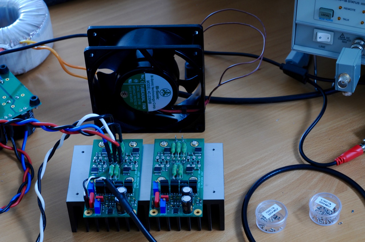
The combination of a really low distortion 1KHz oscillator, a half-way decent 1KHz notch and a HP3585B spec an has me analysing my poor amplifiers to death. It started with just measuring them, now it's progressed to burning my fingers swapping out parts.
Here's the amp I'm working with. It's a slight adaptation of the AEM6000. The difference is that I've dispensed with the differential-symmetrical VAS in favour of a straight symmetrical one:
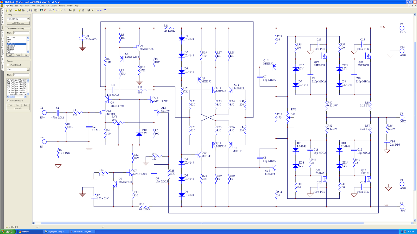
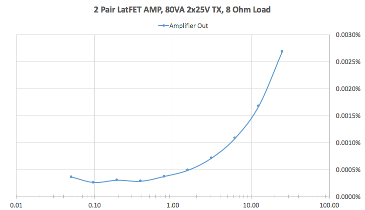
I built one as per the schematic, using on-semi MJE340 & 350s for the second stage and the VAS. It works very well. I measure THD better than 0.0005% up to around 2W output, degrading from there due to the 2x25 transformer I'm testing with, which isn't really big enough for the job:
One substitution I tried this morning is KSC3503 & KSA1381s, for both sides of the VAS (Q16 & Q18), and the pairs in the second stage (Q11-14). My reasoning for the substitution is that they're faster than the MJE parts, and especially in the second stage lower current parts will be an improvement.
It is and it isn't. there was little trimming to get the output stage bias set to 100mA per transistor, which is good, and the amp appears to be very stable. So much so that I dropped the compensation caps back to 10p with no sign of oscillation (though it's early days yet).
However I'm getting very strange distortion figures compared to what I was getting for the pedestrian MJE parts. One of the nice things about the (otherwise tedious) method of getting THD with a spectrum analyser is that I write down every harmonic voltage. With the KSC/KSA parts I'm consistently about 2-3dB better for odd harmonics, but consistently much worse (2dB at 12.5W out, rising to 20dB under a watt) for H2, with H4 being worse by about 4dB across the board.
I've been trying to figure out what's clobbering it. One possibility I hit on was that the commonly available KSA parts are E sort, with 100-200 Hfe, whereas the KSC parts are D sort (60-120). I'm thinking the difference in Hfe is the culprit.
I'm wondering where to go from here? Are E sort KSC3503s readily available? Should I perhaps try deliberately mismatching resistors to compensate? Perhaps I could build a quick circuit to test Hfe and sort the transistors I've got - out of 25 of each I've gotta find some that match...
Here's the amp I'm working with. It's a slight adaptation of the AEM6000. The difference is that I've dispensed with the differential-symmetrical VAS in favour of a straight symmetrical one:
I built one as per the schematic, using on-semi MJE340 & 350s for the second stage and the VAS. It works very well. I measure THD better than 0.0005% up to around 2W output, degrading from there due to the 2x25 transformer I'm testing with, which isn't really big enough for the job:
One substitution I tried this morning is KSC3503 & KSA1381s, for both sides of the VAS (Q16 & Q18), and the pairs in the second stage (Q11-14). My reasoning for the substitution is that they're faster than the MJE parts, and especially in the second stage lower current parts will be an improvement.
It is and it isn't. there was little trimming to get the output stage bias set to 100mA per transistor, which is good, and the amp appears to be very stable. So much so that I dropped the compensation caps back to 10p with no sign of oscillation (though it's early days yet).
However I'm getting very strange distortion figures compared to what I was getting for the pedestrian MJE parts. One of the nice things about the (otherwise tedious) method of getting THD with a spectrum analyser is that I write down every harmonic voltage. With the KSC/KSA parts I'm consistently about 2-3dB better for odd harmonics, but consistently much worse (2dB at 12.5W out, rising to 20dB under a watt) for H2, with H4 being worse by about 4dB across the board.
I've been trying to figure out what's clobbering it. One possibility I hit on was that the commonly available KSA parts are E sort, with 100-200 Hfe, whereas the KSC parts are D sort (60-120). I'm thinking the difference in Hfe is the culprit.
I'm wondering where to go from here? Are E sort KSC3503s readily available? Should I perhaps try deliberately mismatching resistors to compensate? Perhaps I could build a quick circuit to test Hfe and sort the transistors I've got - out of 25 of each I've gotta find some that match...
Last edited:
Hi Suzyj,
Yes, it looks like the top and the bottom halves of the symmetric LTPs and VAS output transistors mismatch.
I'm using 3503/1381 (or lower voltage 3502/1380) transistors extensively, matching them in a way that their h21 difference stays within 2x ratio, keeping that even harmonics increase at acceptable level.
Cheers,
Valery
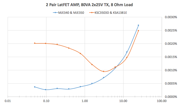
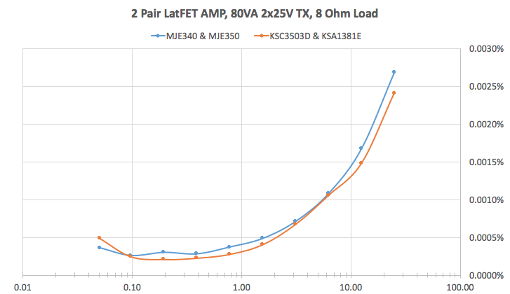
This is really confusing me. Before I swap more parts on this amp I thought it pertinent to properly measure it, so I could get a better understanding on what's happening. I made three comparison plots between this amp and the MJE "benchmark" one; first of overall distortion, then odd harmonics, and finally even harmonics.
Overall:
Odd harmonics only:
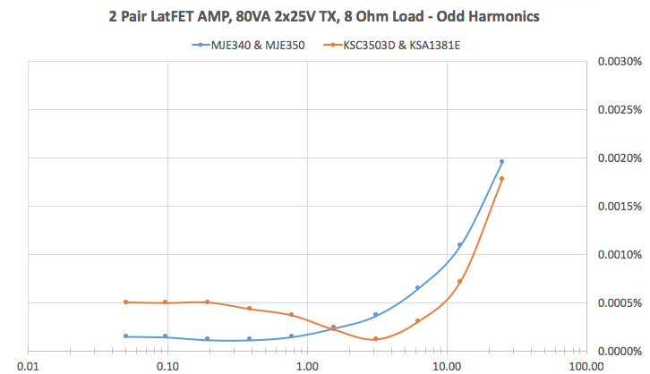
Even harmonics only:
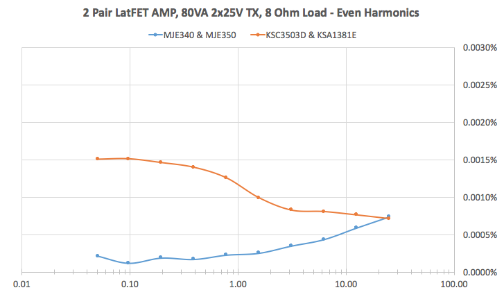
Odd harmonics are well suppressed for both amps, rising only when we run out of supply. As I mentioned previously the KSC/KSA parts perform a little better in clipping. Even harmonics are completely different though (all second order).
Next I made a very simple fixture to test transistor Hfe - essentially a (-)5V lab supply with an ammeter in series on the collector, with the base pulled to (-)5V via a 100K resistor. I went through my stock of transistors and found all my KSC3503D transistors are between 80-85 (drawing about 3.5mA on the fixture). The KSA1381E's match similarly to one another, with a spread between 120-125. This is because they're all Fairchild product, all from the same tube.
My MJE340s and MJE350s show more diversity but are really pretty low gain. My MJE350s range from 60 to 95, and my MJE340s go from 80 to 125.
Next I made C, D, E, and F models for the KSA3803 & KSC1381 in LTspice, to see what effect mismatch had on simulation rather than reality:
.MODEL KSA1381C PNP IS=5.5544E-14 BF=50 BR=1.592 ISE=2.0546f NE=1.5 ISC=3.24807E-10 NC=2 VAF=580 VAR=100 IKF=0.2163 IKR=0.087544 RB=10.18 RE=0.0512 RC=4.072 CJE=9.572p VJE=0.748 MJE=0.371 FC=0.5 CJC=1.147p VJC=0.541 MJC=0.329 TF=1.0312E-09 XTB=0.907 EG=0.62 XTI=3
.MODEL KSC3503C NPN IS=2.0893E-14 BF=50 NF=1 BR=7.655 NR=1.007 ISE=4.3652E-14 NE=1.5 ISC=1.2598n NC=2 VAF=717.25 VAR=13.16 IKF=0.2512 IKR=0.0832 RB=2.98 RBM=0.001 IRB=0.001 RE=0.5305 RC=0.9 QCO=0.05 RCO=50.1187 VO=2.476 GAMMA=1.8231E-7 CJE=6.6039E-11 VJE=0.7017 MJE=0.3253 FC=0.5 CJC=6.6072p VJC=0.5 MJC=0.2439 XCJC=0.6488 XTB=1.4089 EG=1.2129 XTI=3 Vceo=300 Icrating=100m mfg=Fairchild
.MODEL KSA1381D PNP IS=5.5544E-14 BF=80 BR=1.592 ISE=2.0546f NE=1.5 ISC=3.24807E-10 NC=2 VAF=580 VAR=100 IKF=0.2163 IKR=0.087544 RB=10.18 RE=0.0512 RC=4.072 CJE=9.572p VJE=0.748 MJE=0.371 FC=0.5 CJC=1.147p VJC=0.541 MJC=0.329 TF=1.0312E-09 XTB=0.907 EG=0.62 XTI=3
.MODEL KSC3503D NPN IS=2.0893E-14 BF=80 NF=1 BR=7.655 NR=1.007 ISE=4.3652E-14 NE=1.5 ISC=1.2598n NC=2 VAF=717.25 VAR=13.16 IKF=0.2512 IKR=0.0832 RB=2.98 RBM=0.001 IRB=0.001 RE=0.5305 RC=0.9 QCO=0.05 RCO=50.1187 VO=2.476 GAMMA=1.8231E-7 CJE=6.6039E-11 VJE=0.7017 MJE=0.3253 FC=0.5 CJC=6.6072p VJC=0.5 MJC=0.2439 XCJC=0.6488 XTB=1.4089 EG=1.2129 XTI=3 Vceo=300 Icrating=100m mfg=Fairchild
.MODEL KSA1381E PNP IS=5.5544E-14 BF=120 BR=1.592 ISE=2.0546f NE=1.5 ISC=3.24807E-10 NC=2 VAF=580 VAR=100 IKF=0.2163 IKR=0.087544 RB=10.18 RE=0.0512 RC=4.072 CJE=9.572p VJE=0.748 MJE=0.371 FC=0.5 CJC=1.147p VJC=0.541 MJC=0.329 TF=1.0312E-09 XTB=0.907 EG=0.62 XTI=3
.MODEL KSC3503E NPN IS=2.0893E-14 BF=120 NF=1 BR=7.655 NR=1.007 ISE=4.3652E-14 NE=1.5 ISC=1.2598n NC=2 VAF=717.25 VAR=13.16 IKF=0.2512 IKR=0.0832 RB=2.98 RBM=0.001 IRB=0.001 RE=0.5305 RC=0.9 QCO=0.05 RCO=50.1187 VO=2.476 GAMMA=1.8231E-7 CJE=6.6039E-11 VJE=0.7017 MJE=0.3253 FC=0.5 CJC=6.6072p VJC=0.5 MJC=0.2439 XCJC=0.6488 XTB=1.4089 EG=1.2129 XTI=3 Vceo=300 Icrating=100m mfg=Fairchild
.MODEL KSA1381F PNP IS=5.5544E-14 BF=200 BR=1.592 ISE=2.0546f NE=1.5 ISC=3.24807E-10 NC=2 VAF=580 VAR=100 IKF=0.2163 IKR=0.087544 RB=10.18 RE=0.0512 RC=4.072 CJE=9.572p VJE=0.748 MJE=0.371 FC=0.5 CJC=1.147p VJC=0.541 MJC=0.329 TF=1.0312E-09 XTB=0.907 EG=0.62 XTI=3
.MODEL KSC3503F NPN IS=2.0893E-14 BF=200 NF=1 BR=7.655 NR=1.007 ISE=4.3652E-14 NE=1.5 ISC=1.2598n NC=2 VAF=717.25 VAR=13.16 IKF=0.2512 IKR=0.0832 RB=2.98 RBM=0.001 IRB=0.001 RE=0.5305 RC=0.9 QCO=0.05 RCO=50.1187 VO=2.476 GAMMA=1.8231E-7 CJE=6.6039E-11 VJE=0.7017 MJE=0.3253 FC=0.5 CJC=6.6072p VJC=0.5 MJC=0.2439 XCJC=0.6488 XTB=1.4089 EG=1.2129 XTI=3 Vceo=300 Icrating=100m mfg=Fairchild
Simulating with deliberately mismatched transistors (KSA3503C & KSC1881F), shows the circuit is actually really tolerant of gain mismatch here. H2 is always suppressed better than H3, and even with the C-F mismatch I'm still simulating 0.0004% at 320mW.
Now I'm wondering if there might be something else wrong with this amplifier. I guess the next step is to measure it's DC operating point for all nodes and compare that to the good one to see if there's anything obviously amiss.
Overall:
Odd harmonics only:
Even harmonics only:
Odd harmonics are well suppressed for both amps, rising only when we run out of supply. As I mentioned previously the KSC/KSA parts perform a little better in clipping. Even harmonics are completely different though (all second order).
Next I made a very simple fixture to test transistor Hfe - essentially a (-)5V lab supply with an ammeter in series on the collector, with the base pulled to (-)5V via a 100K resistor. I went through my stock of transistors and found all my KSC3503D transistors are between 80-85 (drawing about 3.5mA on the fixture). The KSA1381E's match similarly to one another, with a spread between 120-125. This is because they're all Fairchild product, all from the same tube.
My MJE340s and MJE350s show more diversity but are really pretty low gain. My MJE350s range from 60 to 95, and my MJE340s go from 80 to 125.
Next I made C, D, E, and F models for the KSA3803 & KSC1381 in LTspice, to see what effect mismatch had on simulation rather than reality:
.MODEL KSA1381C PNP IS=5.5544E-14 BF=50 BR=1.592 ISE=2.0546f NE=1.5 ISC=3.24807E-10 NC=2 VAF=580 VAR=100 IKF=0.2163 IKR=0.087544 RB=10.18 RE=0.0512 RC=4.072 CJE=9.572p VJE=0.748 MJE=0.371 FC=0.5 CJC=1.147p VJC=0.541 MJC=0.329 TF=1.0312E-09 XTB=0.907 EG=0.62 XTI=3
.MODEL KSC3503C NPN IS=2.0893E-14 BF=50 NF=1 BR=7.655 NR=1.007 ISE=4.3652E-14 NE=1.5 ISC=1.2598n NC=2 VAF=717.25 VAR=13.16 IKF=0.2512 IKR=0.0832 RB=2.98 RBM=0.001 IRB=0.001 RE=0.5305 RC=0.9 QCO=0.05 RCO=50.1187 VO=2.476 GAMMA=1.8231E-7 CJE=6.6039E-11 VJE=0.7017 MJE=0.3253 FC=0.5 CJC=6.6072p VJC=0.5 MJC=0.2439 XCJC=0.6488 XTB=1.4089 EG=1.2129 XTI=3 Vceo=300 Icrating=100m mfg=Fairchild
.MODEL KSA1381D PNP IS=5.5544E-14 BF=80 BR=1.592 ISE=2.0546f NE=1.5 ISC=3.24807E-10 NC=2 VAF=580 VAR=100 IKF=0.2163 IKR=0.087544 RB=10.18 RE=0.0512 RC=4.072 CJE=9.572p VJE=0.748 MJE=0.371 FC=0.5 CJC=1.147p VJC=0.541 MJC=0.329 TF=1.0312E-09 XTB=0.907 EG=0.62 XTI=3
.MODEL KSC3503D NPN IS=2.0893E-14 BF=80 NF=1 BR=7.655 NR=1.007 ISE=4.3652E-14 NE=1.5 ISC=1.2598n NC=2 VAF=717.25 VAR=13.16 IKF=0.2512 IKR=0.0832 RB=2.98 RBM=0.001 IRB=0.001 RE=0.5305 RC=0.9 QCO=0.05 RCO=50.1187 VO=2.476 GAMMA=1.8231E-7 CJE=6.6039E-11 VJE=0.7017 MJE=0.3253 FC=0.5 CJC=6.6072p VJC=0.5 MJC=0.2439 XCJC=0.6488 XTB=1.4089 EG=1.2129 XTI=3 Vceo=300 Icrating=100m mfg=Fairchild
.MODEL KSA1381E PNP IS=5.5544E-14 BF=120 BR=1.592 ISE=2.0546f NE=1.5 ISC=3.24807E-10 NC=2 VAF=580 VAR=100 IKF=0.2163 IKR=0.087544 RB=10.18 RE=0.0512 RC=4.072 CJE=9.572p VJE=0.748 MJE=0.371 FC=0.5 CJC=1.147p VJC=0.541 MJC=0.329 TF=1.0312E-09 XTB=0.907 EG=0.62 XTI=3
.MODEL KSC3503E NPN IS=2.0893E-14 BF=120 NF=1 BR=7.655 NR=1.007 ISE=4.3652E-14 NE=1.5 ISC=1.2598n NC=2 VAF=717.25 VAR=13.16 IKF=0.2512 IKR=0.0832 RB=2.98 RBM=0.001 IRB=0.001 RE=0.5305 RC=0.9 QCO=0.05 RCO=50.1187 VO=2.476 GAMMA=1.8231E-7 CJE=6.6039E-11 VJE=0.7017 MJE=0.3253 FC=0.5 CJC=6.6072p VJC=0.5 MJC=0.2439 XCJC=0.6488 XTB=1.4089 EG=1.2129 XTI=3 Vceo=300 Icrating=100m mfg=Fairchild
.MODEL KSA1381F PNP IS=5.5544E-14 BF=200 BR=1.592 ISE=2.0546f NE=1.5 ISC=3.24807E-10 NC=2 VAF=580 VAR=100 IKF=0.2163 IKR=0.087544 RB=10.18 RE=0.0512 RC=4.072 CJE=9.572p VJE=0.748 MJE=0.371 FC=0.5 CJC=1.147p VJC=0.541 MJC=0.329 TF=1.0312E-09 XTB=0.907 EG=0.62 XTI=3
.MODEL KSC3503F NPN IS=2.0893E-14 BF=200 NF=1 BR=7.655 NR=1.007 ISE=4.3652E-14 NE=1.5 ISC=1.2598n NC=2 VAF=717.25 VAR=13.16 IKF=0.2512 IKR=0.0832 RB=2.98 RBM=0.001 IRB=0.001 RE=0.5305 RC=0.9 QCO=0.05 RCO=50.1187 VO=2.476 GAMMA=1.8231E-7 CJE=6.6039E-11 VJE=0.7017 MJE=0.3253 FC=0.5 CJC=6.6072p VJC=0.5 MJC=0.2439 XCJC=0.6488 XTB=1.4089 EG=1.2129 XTI=3 Vceo=300 Icrating=100m mfg=Fairchild
Simulating with deliberately mismatched transistors (KSA3503C & KSC1881F), shows the circuit is actually really tolerant of gain mismatch here. H2 is always suppressed better than H3, and even with the C-F mismatch I'm still simulating 0.0004% at 320mW.
Now I'm wondering if there might be something else wrong with this amplifier. I guess the next step is to measure it's DC operating point for all nodes and compare that to the good one to see if there's anything obviously amiss.
Looking at the diagrams, it may seem, the output stage of the red channel is slightly under-biased, leading to crossover distortion increase at low swing. However, crossover distortion is normally rather wideband, influencing the odd harmonics as well as the even ones,,,
Anyway, checking DC operating points makes sense - something is not right.
Anyway, checking DC operating points makes sense - something is not right.
Got it. It should have been obvious from the drop in H2 at higher power levels, but hey, I'm dense.
The two 2SJ162s I've got on this board measured very different. With a warmed up amplifier I'm getting 14mV across one source resistor and 20mV across the other. Cold it's 22mV and 29mV.
I went to remove the board from the heatsink, so I could replace the 2SJ162s. I found I hadn't torqued up the screw holding one of them down, so the poor thing was frying. So rather than remove it I torqued it up, repeated my measurements, and am suitably happy. I think I'll stick with the KSA/KSC parts, but I really need to retest at 10KHz, as that's where most of the improvement from these parts will likely be found.
Ah! Cool
Now it makes sense. So, in fact, one of four output MOSFETs was biased differently from the others - that explains assymetry and thus affecting the even harmonics stronger than the odd ones.
Yup, that's exactly right. Chalk another one up for negative temperature coefficient lateral MOSFETs. I reckon if I'd tried this with bipolars or vertical MOSFETs I'd have started a fire
")
Hey, here's a cool one. I'd attributed the increase in THD beyond 10W or so to using a little 80VA, 2x25V transformer for test. I grabbed it because it was pretty-much ready to go.
To see how the amp went out to 100W, which is really what I've designed it for, I grabbed a 300VA 2x40V toroidal and wired that up.
The result: practically no change in THD at high power levels. Very strange and not at all promising.
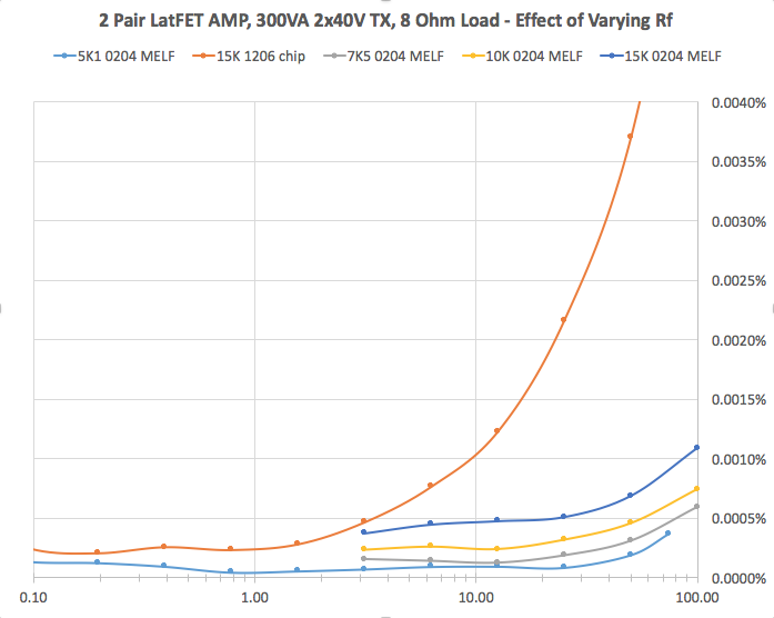
I thought I'd try swapping Rf for something a little lower, on the basis that this amp appears to be very stable, so throwing a bit more negative feedback in won't hurt. Spice sims show no nasty peaking or misbehaviour even with 5K Rf (gain of 6).
So in goes a 5K1 0204 MELF. THD performance is now not just better, but better to the point where distortion products are in the noise, across the board. Much better than they should have been. The amp is still nice and stable.
Next I tried a 7K5 and a 10K MELF for Rf. Slightly worse performance than the 5K1, but reasonably so. Then it dawned on me that the original 15K one was a 1206 chip resistor. So I substituted a 15K MELK, and tested that, and there you go. I'm thinking the chip resistor just wasn't really happy dissipating the 20-50 odd mW that it needs to in this position.
I've gotten into a habit of late of just grabbing chip resistors, because they don't roll around. I think now I'm going to throw them out and completely go back to MELFs.
To see how the amp went out to 100W, which is really what I've designed it for, I grabbed a 300VA 2x40V toroidal and wired that up.
The result: practically no change in THD at high power levels. Very strange and not at all promising.
I thought I'd try swapping Rf for something a little lower, on the basis that this amp appears to be very stable, so throwing a bit more negative feedback in won't hurt. Spice sims show no nasty peaking or misbehaviour even with 5K Rf (gain of 6).
So in goes a 5K1 0204 MELF. THD performance is now not just better, but better to the point where distortion products are in the noise, across the board. Much better than they should have been. The amp is still nice and stable.
Next I tried a 7K5 and a 10K MELF for Rf. Slightly worse performance than the 5K1, but reasonably so. Then it dawned on me that the original 15K one was a 1206 chip resistor. So I substituted a 15K MELK, and tested that, and there you go. I'm thinking the chip resistor just wasn't really happy dissipating the 20-50 odd mW that it needs to in this position.
I've gotten into a habit of late of just grabbing chip resistors, because they don't roll around. I think now I'm going to throw them out and completely go back to MELFs.
Last edited:
OK, transformer of the proper power rating brings performance at high power to the level, where it should be.
Do you mean Rf is R48 at the schematic in post #1?
But in this case, changing its value, you also change the voltage gain accordingly.
Even 15K value gives us the the gain of 24db gain, which is lower than 29db - "de facto" standard for a power amp, requiring R48 = 27K in this case.
Bringing the value down to 5.1K, brings the gain down to 15.6db accordingly.
Well, MELF resistors are higher quality ones, than the chip ones in general, however, in my experience, the good chip ones work fine in this position. It becomes more important in CFA designs with low-impedance NFB networks, dissipating up to some 3W or so at high swing.
That's an interesting observation, looking at those graphs the difference between the15k MELF and MELK is relatively small at 3 Watts, and then suddenly the curves departs, do you know what type of resistors they are?
Or is there something else that makes MELK's inferior to MELF's?
Or is there something else that makes MELK's inferior to MELF's?
The chip resistor is a generic 1206 thick-film 5% 250mW part: http://www.mouser.com/ds/2/447/PYu-RC1206_51_RoHS_L-4-349080.pdf
The MELFs are Beyschlag 400mW MMA 0204 1% ones: http://www.vishay.com/docs/28713/melfprof.pdf
I'm wondering if perhaps the low thermal mass of the chip resistor, coupled with running it vaguely near it's dissipation limit, means that it heats up on the peaks of the waveform, with a change in resistance, and hence distortion. The MELF has ~10x the mass, plus twice the dissipation.
Yes, Rf is labelled R48 on the schematic. My point really was the comparison of the two "15K" (x16) plots, one with a MELF resistor and the other with a 1206 chip resistor, both of which were measured with the same 300VA transformer. They should be identical but they're very different.
This is the first I've heard of any standard as to the gain of an audio power amp. My design rationale has always been to see how low I could push the gain whilst maintaining stability, on the basis that it improves distortion performance (as the graph clearly demonstrates). A few more dB can always be added to the front end with an opamp, with the added benefit of pushing the noise floor down as well.
If you look closely at the graph you can see where my 4V RMS source runs out of steam, providing a maximum of 24.4V RMS (74W into 8 Ohms) rather than the more usual 28.8V RMS I've been testing to.
Last edited:
Skimming quickly through the PDF's with risk of inaccuracy, I see from the data sheet the 1206's TempCo are +/-100ppm for R= 10 > 10x10^6 (<10R OR >10x10^6 => +/-200ppm), while the MELF is +/-25 or +/-50ppm (depending on which type), probably the resistor material is playing a noticeable role too.
Please verify in case I have missed something.
It may be prudent choosing low ppm types in critical paths of the amplifier.
ps. re. MELK, I meant those 1206 chips, not the sharpest at present as I haven't done or thinking electronics for some years.
edit: sweet, nice and tidy looking boards.

Please verify in case I have missed something.
It may be prudent choosing low ppm types in critical paths of the amplifier.
ps. re. MELK, I meant those 1206 chips, not the sharpest at present as I haven't done or thinking electronics for some years.
edit: sweet, nice and tidy looking boards.
Last edited:
... 1206 thick-film 5% 250mW part: ...
These are known to be fairly bad.
Bruce Hofer (the founder of Audio Precision) has an informative discussion of resistor, and other component, distortion that is easy to find on-line.
He confirms the idea that lower tempco is better, at least to the point of bulk foil resistors that perform well but not as well as expected from the tiny tempco.
Best wishes
David
Last edited:
Are you talking about NFB resistors here? Rf?Hey, here's a cool one. I'd attributed the increase in THD beyond 10W or so to using a little 80VA, 2x25V transformer for test. I grabbed it because it was pretty-much ready to go.
To see how the amp went out to 100W, which is really what I've designed it for, I grabbed a 300VA 2x40V toroidal and wired that up.
The result: practically no change in THD at high power levels. Very strange and not at all promising.
I thought I'd try swapping Rf for something a little lower, on the basis that this amp appears to be very stable, so throwing a bit more negative feedback in won't hurt. Spice sims show no nasty peaking or misbehaviour even with 5K Rf (gain of 6).
So in goes a 5K1 0204 MELF. THD performance is now not just better, but better to the point where distortion products are in the noise, across the board. Much better than they should have been. The amp is still nice and stable.
Next I tried a 7K5 and a 10K MELF for Rf. Slightly worse performance than the 5K1, but reasonably so. Then it dawned on me that the original 15K one was a 1206 chip resistor. So I substituted a 15K MELK, and tested that, and there you go. I'm thinking the chip resistor just wasn't really happy dissipating the 20-50 odd mW that it needs to in this position.
I've gotten into a habit of late of just grabbing chip resistors, because they don't roll around. I think now I'm going to throw them out and completely go back to MELFs.
I have been posting about little kernels of wisdom I have picked up from others over the years.
When I tell them that the NFB resistors must have massively more Pmax capability than what the amplifier pushes through the NFB string, most Builders here won't believe me.
Are your results showing that the melf (helical metal film around a circular ceramic core) behave better than a 1206 SMD where the metal film is simply adhering to the flat face of the ceramic substrate?
This would seem to indicate that it's not just Pmax but the shape of the film that is having an effect. Is it something more than a different tempco?
Through hole leaded resistors are formed in a similar manner to melf. Could you repeat using a leaded Rf?
edit, I just checked the .pdf of the 1206 smd. You used a MOX resistor. tempco is 100ppn/C, most MOX are ~300ppm/C at least you picked a slightly better MOX.
Change to a good 25ppm/C metal oxide (thin film) 805 and use five 3k in series to get similar Pmax to your melf rating. If you have straight bit of trace you can insert the 805 into the trace for series connection.
Last edited:
When you reduce the gain of an amplifier you need to increase the input to give the same output. In this case you have increased the input by a factor of three.The chip resistor is a generic 1206 thick-film 5% 250mW part: http://www.mouser.com/ds/2/447/PYu-RC1206_51_RoHS_L-4-349080.pdf
The MELFs are Beyschlag 400mW MMA 0204 1% ones: http://www.vishay.com/docs/28713/melfprof.pdf
I'm wondering if perhaps the low thermal mass of the chip resistor, coupled with running it vaguely near it's dissipation limit, means that it heats up on the peaks of the waveform, with a change in resistance, and hence distortion. The MELF has ~10x the mass, plus twice the dissipation.
Yes, Rf is labelled R48 on the schematic. My point really was the comparison of the two "15K" (x16) plots, one with a MELF resistor and the other with a 1206 chip resistor, both of which were measured with the same 300VA transformer. They should be identical but they're very different.
This is the first I've heard of any standard as to the gain of an audio power amp. My design rationale has always been to see how low I could push the gain whilst maintaining stability, on the basis that it improves distortion performance (as the graph clearly demonstrates). A few more dB can always be added to the front end with an opamp, with the added benefit of pushing the noise floor down as well.
If you look closely at the graph you can see where my 4V RMS source runs out of steam, providing a maximum of 24.4V RMS (74W into 8 Ohms) rather than the more usual 28.8V RMS I've been testing to.
For most Power Amplifiers where the gain is +26dB to +34dB, the quite small input voltage does not show as being sensitive to common mode distortion due to high voltage swings at the input.
But when you reduce the gain such that you need ten times the voltage swing at the input, then common mode distortion will probably show up. Opamps with gain around 2times (+6dB) compared to 100times (+40dB) do show this change in common mode distortion. A couple of power amplifier designers have shown this in their publications.
Would this common mode show more at HF, or all through the passband?
Looking again at the spread of distortions as you change the gain.
Increased feedback reduces the distortion. Three times as much feedback roughly divides the distorition by three. Is that what your group of 4 plots is showing?
Last edited:
That's exactly right Andrew. You'll note I'm running the voltage gain of the input diffamp lower than I probably could, with 18K loads. With ~1mA down either side of the diffamp, 12V across the jFETs, and +/-60V supply, I've got ~+/-30V at the input before I run out of common range. In my experience running out of common mode range simply causes clipping, so much the same issue as hitting the rails at any other point in the amp, with distortion products rising evenly everywhere.
My source is running at +/-12V, hence the 4V RMS max. The source easily achieves better than 1ppm THD into a 1K6 load (my passive notch). Zin for this amp is ~100K, so maintaining the 1ppm figure with the amp as a load is reasonable, I think.
Yes, the plots show (with the exception of the 15K chip), that using more OLG in feedback pushes the THD down proportionally.
- Status
- This old topic is closed. If you want to reopen this topic, contact a moderator using the "Report Post" button.
- Home
- Amplifiers
- Solid State
- Even order distortion in symmetrical amp