I own two Cyrus Two amplfiers, an Issue 6 (plastic case) and an Issue 7 (die-cast case). Both amplifiers are eBay "rescue" amps (bought as spares or repair) which I have re-capped, adjusted bias current etc and I believe they sound as good as the original production models. Although the circuit designs are virtually identical, they do sound noticeably different and I investigated this difference to try to understand the reason.
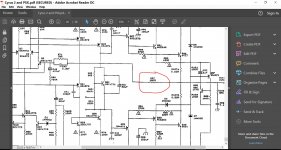
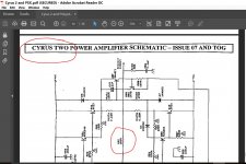
The only significant difference in design is that the Issue 7 version has a 150 Ohm resistor in the negative feedback loop, immediately after the feedback take-off point. If I short this resistor on both channels, the Issue 7 sounds almost exactly the same as the earlier Issue 6. So what's the audible difference? Issue 6 (without the 150R feedback resistor) has far greater high frequency extension which manifests itself to me in a more realistic, live presentation of percussion instruments such as cymbals, hi-hats etc and also string and wind instruments. In fact, it may be too much for some audio systems that already have a "bright" presentation. I am guessing the 150R resistor was added as a high-frequency "damper" to control possible overshoot or inductive ringing into difficult speaker loads or maybe just to isolate the feedback network from the speaker? It may have been added to improve phase and gain margin. Regardless of the design philosophy, its seems to have a pronounced affect on the musical presentation and others may want to experiment too.")
The only significant difference in design is that the Issue 7 version has a 150 Ohm resistor in the negative feedback loop, immediately after the feedback take-off point. If I short this resistor on both channels, the Issue 7 sounds almost exactly the same as the earlier Issue 6. So what's the audible difference? Issue 6 (without the 150R feedback resistor) has far greater high frequency extension which manifests itself to me in a more realistic, live presentation of percussion instruments such as cymbals, hi-hats etc and also string and wind instruments. In fact, it may be too much for some audio systems that already have a "bright" presentation. I am guessing the 150R resistor was added as a high-frequency "damper" to control possible overshoot or inductive ringing into difficult speaker loads or maybe just to isolate the feedback network from the speaker? It may have been added to improve phase and gain margin. Regardless of the design philosophy, its seems to have a pronounced affect on the musical presentation and others may want to experiment too.
that 150r will have virtually no effect on the 75k upper leg NFB resistance.
It will have a significant effect on the parallel 3p3F capacitor from 600kHz to 320MHz.
Something to do with interference rejection from the speaker lead?
I wonder if the R+C of Cyrus3 was found to be a bit better at keeping out interference from the -IN node.
It will have a significant effect on the parallel 3p3F capacitor from 600kHz to 320MHz.
Something to do with interference rejection from the speaker lead?
I wonder if the R+C of Cyrus3 was found to be a bit better at keeping out interference from the -IN node.
Last edited:
It is common practice to fine tune the stability margins with the extra C across the NFB upper resistance.
but that brings with it the susceptability to RF interference from the speaker cables.
The only thing attenuating that speaker lead interference is the Thiele Network.
That is partly why I adopted the Pi version to gain a little bit of extra attenuation of interference.
but that brings with it the susceptability to RF interference from the speaker cables.
The only thing attenuating that speaker lead interference is the Thiele Network.
That is partly why I adopted the Pi version to gain a little bit of extra attenuation of interference.
Mooly, thanks for sorting out the correct Cyrus Two schematic showing the "rogue" resistor.
Andrew, I realised that the 150R will have virtually no affect on feedback gain being within the 2% tolerance band of the 75K feedback resistor so it had to be added for some other reason. You mention the interaction with the 3p3 parallel capacitor at much higher frequencies but the effect of that resistor is heard very clearly by my 56-year old ears within the audible range and confirmed by comparison with the resistor-free Cyrus Issue 6. Maybe it is reacting with a higher parasitic capacitance in the feedback loop layout but we wouldn't expect much more than additional 5 - 10pF?
I had hoped someone else with the same build Cyrus Two would check this phenomenon as a sanity check. The difference is quite marked and you might be pleasantly (or unpleasantly!) surprised
Amplifiers are not really purely linear.
They are affected by out of band interference.
That can be added as in band artefacts that are audible due to the non linearities.
That is indicated by the 19+20kHz distortion test. 19+20kHz should not be heard by the majority of us, but Intermodulation brings some of the distortion down to 1kHz where in the absense of other strong signal would be audible as "something is wrong" with the sound.
Andrew, good explanation and it seems to confirm another audible effect I hear - a sort of low level "ghost" sound shadowing the start of vocals and instruments.
Ok, so this resistor was added to reduce or filter out high frequency inter-modulation distortion artefacts. However, its effect is clearly noticeable across the audible frequency range, more marked for upper frequencies. Since I prefer my drums and percussion to sound more natural, I will adjust the resistor value down to reduce the "ghosting" effect but retain the wider frequency response.
Ok, so this resistor was added to reduce or filter out high frequency inter-modulation distortion artefacts. However, its effect is clearly noticeable across the audible frequency range, more marked for upper frequencies. Since I prefer my drums and percussion to sound more natural, I will adjust the resistor value down to reduce the "ghosting" effect but retain the wider frequency response.
The Cyrus 2 is old fashioned through hole PCB assembly.
It should be possible to copy the Cyrus 3 NFB and listen to that as well.
It is also very easy to add the second Zobel across the output terminals to convert a conventional Thiele Network to the Pi version. Another experiment worth trying.
I wish I still had my Cyrus 2. I loaned it out and it never came back.
Hi Andrew, you learned the hard way about "lending" out your Cyrus Two. Do you have a schematic for the Cyrus 3 NFB loop? However, this resistor revision and resulting audible difference was between Cyrus Two Issue 6 and the later Issue 7. I think the Cyrus 3 was the first SMD component version that was generally panned as not being as good as the Cyrus Two.
Cyrus 3 Power Amplifier schematic.
C502 should be smaller, or C520 should be bigger.
As shown there will be a small amount of AC voltage across the NFB capacitor. This will add a very small amount of distortion to the bass.
I would change C502 to 1u5F plastic film (or 1uF||470nF) and change C520 to 150uF with signal diode bypass.
I have no idea why they thought it necessary to increase the amp gain to +34.6dB.
Attachments
Last edited:
Andrew, thanks for the Cyrus 3 schematic. I can now see the product development path from Cyrus Two to Cyrus 3. Much or the core design is the same but it is clear the Cyrus 3 designer made significant changes to the NFB and frequency compensation configuration, as well as implementing the digital interface for micro-controller control of bias settings and CCS switch on/off. I notice the power supply and decoupling capacitors etc are significantly up-rated from the earlier Two design which is something I already do as part of a Cyrus Two re-cap. As you pointed out, I can see some dubious design choices (low value feedback capacitor, bias setting etc) that might make the Cyrus 3 sound inferior to the Cyrus Two but think we are probably going off-topic.
I am surprised that no Cyrus Two Issue 7 owners have been curious enough to try this simple resistor modification mentioned and report back their own findings.
I am surprised that no Cyrus Two Issue 7 owners have been curious enough to try this simple resistor modification mentioned and report back their own findings.
- Status
- This old topic is closed. If you want to reopen this topic, contact a moderator using the "Report Post" button.
- Home
- Amplifiers
- Solid State
- Cyrus Two feedback resistor modification