I am working with an amp which has no dc offset adjustment. (schematics attached)
I seen some other threads which touched on the subject. However I would like to get some input as to which method would be the approach needed for this specific circuit layout. Thanks
I seen some other threads which touched on the subject. However I would like to get some input as to which method would be the approach needed for this specific circuit layout. Thanks
Attachments
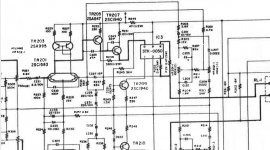
An offset trim is pointless in this circuit - DC balance varies by severals tens of kOhms depending on the position of the bass control. Input transistors seem to run at close to half a mA, so assuming an Ib of roughly a microamp we're looking at something between maybe 30 mV one way and 70 mV the other. If it's a lot more, assume either some bad electrolytics (C221 is not going to last there unless a low-leakage type) or a leaky input transistor. It would appear the 2SC1583 is being operated near its Vce limits, a replacement could be fabricated using two matched 2SC945s or preferably something rated a bit higher (1845 maybe).
AC impedance balance in this circuit isn't exactly great either, we're talking 560 ohms vs. anything from 2k2 to >50k. Not great given the input stage current.
AC impedance balance in this circuit isn't exactly great either, we're talking 560 ohms vs. anything from 2k2 to >50k. Not great given the input stage current.
An offset trim is pointless in this circuit - DC balance varies by severals tens of kOhms depending on the position of the bass control. Input transistors seem to run at close to half a mA, so assuming an Ib of roughly a microamp we're looking at something between maybe 30 mV one way and 70 mV the other. If it's a lot more, assume either some bad electrolytics (C221 is not going to last there unless a low-leakage type) or a leaky input transistor. It would appear the 2SC1583 is being operated near its Vce limits, a replacement could be fabricated using two matched 2SC945s or preferably something rated a bit higher (1845 maybe).
All electrolytic caps and resistors (except for the larger metal oxide)have been replaced.
I double checked to see if there any mistakes concerning the components replaced, everything checked good. Afterwards when I checked for DC at the output, it read -6mv on one channel and -48 on the other. I swapped the 5 pin transistors from the right channel to the left and vice versa. The exact DC readings were then reversed between the channels.
I wanted to find out why there was only -6mv on one of the channels. So I started doing
some gain testing on the 5 pin transistors. Turns out the channel with the lowest DC actually has a
2SC1583 in which the dual transistor pair no longer matches. One of the transistors in the 1583 has an hfe of 222 the other is 167. I pulled both 5 pin transistors for that channel.
I then replaced the 2SC1583 with a matched pair of KSC1845, and replaced the 2SA995 with a matched pair of KSC992. The results? DC at the output is about -36mv.
AC impedance balance in this circuit isn't exactly great either, we're talking 560 ohms vs. anything from 2k2 to >50k. Not great given the input stage current.
When you say 560 ohms, are you referring to a specific resistor used? (There are 3 total in the amp) Or did you calculate a resistance through multiple components? Would you recommend increasing it?
Last edited:
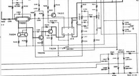
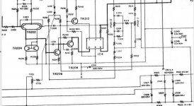
A possebility, other side same thing
Mona
Thanks for the schematic edit. I'll experiment with it and see how it goes.
- Status
- This old topic is closed. If you want to reopen this topic, contact a moderator using the "Report Post" button.
- Home
- Amplifiers
- Solid State
- Adding DC offset pot