I dont really want to mess around with it as it sounds good!
This reminds me an old mono block amp I had a few years back with bias isssue. I attempted to adjust it and it even had the testing posts but the problem was it never stayed stable! warm up would keep rising then after like 5-15 minutes it just kept dropping then kept climbing I gave up! Its not like the values were close either! and because it was mono it had minus and plus terminals not left and right!!!??!?!?! Any thoughts? So mosfet is FET? didnt know that
This reminds me an old mono block amp I had a few years back with bias isssue. I attempted to adjust it and it even had the testing posts but the problem was it never stayed stable! warm up would keep rising then after like 5-15 minutes it just kept dropping then kept climbing I gave up! Its not like the values were close either! and because it was mono it had minus and plus terminals not left and right!!!??!?!?! Any thoughts? So mosfet is FET? didnt know that
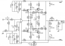
This old thread has the schematic for the VA100 II which is not greatly different and shows the simplicity of the power amplifier design. http://www.diyaudio.com/forums/solid-state/86517-aura-va100-evoluton-ii.html
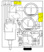
The PSU on all VA100 versions I think, is connected to each channel's power amplifier via separate bundles of leads, header pins and a socket so it wouldn't be too difficult to make up a break-out link to fit between the pins and socket of each power connector and insert say, a 0.22 ohm 1-2W resistor in the positive or negative supply rail connection (+ or - 50V) of one channel and measure the voltage drop across this when the amplifier is idling with no speakers or input connected.
The current is calculated using Ohm's law, as in most bias setting procedures so for a 0.22R resistor with a suggested 100mA current, the voltage drop would be 22mV. However, the amplifier will draw more than the output stage current alone and I would allow for a further 15mA, bringing the resistor's voltage drop up to 25mV. Repeat for the other channel using the same arrangement for its power connector. The current setting of 100mA for lateral Mosfets is not critical but normal and correct as Mooly stated, for a neutral (neither positive or negative) bias temperature coefficient and a wise compromise of heat versus distortion.
Attachments
I dont really want to mess around with it as it sounds good!
This reminds me an old mono block amp I had a few years back with bias isssue. I attempted to adjust it and it even had the testing posts but the problem was it never stayed stable! warm up would keep rising then after like 5-15 minutes it just kept dropping then kept climbing I gave up! Its not like the values were close either! and because it was mono it had minus and plus terminals not left and right!!!??!?!?! Any thoughts? So mosfet is FET? didnt know that
Bias that wanders and varies as the amp warms is down to (poor) design of the circuit. That said it is normal in most amps to see some variation.
The current rises as the output transistors warm (their intrinsic characteristics alter slightly with temperature, which all things being equal manifests as a rise in current) and so normally there is a compensatory device (another transistor bolted to the heatsink) that can be used to cancel out the variation. It works and works well but there is thermal lag, the output devices heat instantly internally and it takes a little while for that to equalise along all the heatsink. So the bias can see saw around for a while.
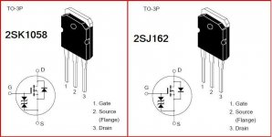
The lateral FET's at 100ma are stable through the whole temperature range of operation and so the set bias should stay put.
Thanks guys I will, 1, try to understand the aura and see if I can fix the bias 2, in the next couple days bring out the old mono block power amp. One works and one doesnt its a cambridge audio I think something 75 and something about the designer Stan Curtis? But mine is different it looks very different but says A75 on the inside. If I recall the guy who sold it to me said it was either 125 or 250 model. I will fish it out and would appreciate any help. I have seen them come up on ebay once or twice too!
What I would suggest for the bias would be to lift (isolate) one of the drains and simply add a 1 ohm over the break. Solder wires to the one ohm and bring those out to your meter so that you have a solid connection with no possibility of twitchy fingers causing a short.
Then just set the bias to the appropriate level which would be 100mv for a 1 ohm.
The other amp would best in a new thread tbh")
Then just set the bias to the appropriate level which would be 100mv for a 1 ohm.
The other amp would best in a new thread tbh
What I would suggest for the bias would be to lift (isolate) one of the drains and simply add a 1 ohm over the break. Solder wires to the one ohm and bring those out to your meter so that you have a solid connection with no possibility of twitchy fingers causing a short.
Then just set the bias to the appropriate level which would be 100mv for a 1 ohm.
The other amp would best in a new thread tbh
Can you write that in martian language because I think I would understand it better!
Heh! How about, unsolder the drain leg and lift it, solder a 1 ohm resistor to the leg and solder the other end of the resistor back to the board. Take meter readings across the resistor (with or without a wire tail to make it easier), and Bob's your uncle.
An externally hosted image should be here but it was not working when we last tested it.
^ As he says. 
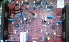
You break the connection to ONE of the Drain terminals. It can be either transistor in the channel in question, it doesn't matter. Then link a 1 ohm across the break and measure the voltage across that 1 ohm.
No speakers and no signal for this.
You break the connection to ONE of the Drain terminals. It can be either transistor in the channel in question, it doesn't matter. Then link a 1 ohm across the break and measure the voltage across that 1 ohm.
No speakers and no signal for this.
Attachments
If there is any DC offset then adding a load will skew the result, albeit only by a few percent unless the DC error is large. Any solid state amp should be 100% stable with no load.
Valve amps are fundamentally different in that regard, and particularly if signal is applied with no load.
Valve amps are fundamentally different in that regard, and particularly if signal is applied with no load.
The voltage is that developed across the 1 ohm and we deduce the current by simple calculation.
If we aim for 100 milliamps current then that means we need to see 100 millivolts across the resistor. V=I*R and all that.
The wattage can be low. Even a 0.25 watt would be OK for testing. W=I*V which is just 10 milliwatts at 0.1 amp current flow.
If we aim for 100 milliamps current then that means we need to see 100 millivolts across the resistor. V=I*R and all that.
The wattage can be low. Even a 0.25 watt would be OK for testing. W=I*V which is just 10 milliwatts at 0.1 amp current flow.
- Status
- This old topic is closed. If you want to reopen this topic, contact a moderator using the "Report Post" button.
- Home
- Amplifiers
- Solid State
- Speaker cone moving not faulty pot