Dear DIY Audio Community,
In this thread I like to discuss a amplifier / speaker protection circuit that I designed.
Foreword:
I once fried a speaker by turning equipment on the wrong order.
As a countermeasure I improvised a circuit to delay speaker connection on power on.
So far so bad.
I like to get rid of the improvised delay circuit and have a real protection circuit instead.
There are a lot of modules available on the market, some even extremely cheap to buy.
I also found lots of circuits.
But none work the way I need them to.
My requirements for a speaker protection circuit:
1. Delayed connection of speaker after power on.
2. Instant speaker disconnection on power off.
3. Quick speaker disconnect in case of DC on amplifier output.
4. Latch relays off when any fault occurred.
5. Can be used for my dual mono design without hard wiring ground of the two amps together.
6. Can be built from parts I have at home or can source easily and cheap.
7. Is component selection invariant.
8. Is supply invariant from 12V to 24V.
9. Can be configured in a lot of ways so that others can make use of it easily.
From the circuits I found I liked the DIY Audio circuit best that is also used for the boards in the DIY Audio store.
It already fulfills requirements 6 and 7 and 8.
But this circuit has serious drawbacks I tried to get rid off.
I spent lots of time developing a circuit that hopefully does what I envisioned.
Circuit description:
The circuit has following modules:
1. AC to DC rectifier
2. Linear regulator
3. Relay status indicator
4. Turn on delay circuit
5. Latch circuit
6. DC detection
7. Instant off on AC loss
Module description in detail:
1. AC to DC
This is a standard rectifier. Nothing to explain.
2. Linear regulator
This is made up of discrete parts and a very basic circuit. I'm not sure whether this is a good design since I've never done any before and don't know the pitfalls. Feedback from the great engineers of the DIY community is very appreciated.
3. Relays status indicator
I used this circuit from the DIY Audio schematic. I find it a nice solution with the blinken light. Just tweaked component values to my needs. The LED blinks until the relays are engaged and then lights constantly.
4. Turn on delay circuit
I started with the DIY Audio schematic but added a Schmitt trigger for clearly defined switching of the relays because this was missing.
5. Latch circuit
A failure is a potentially catastrophic event. Should the speaker survive the first wave and the relays succeed to disconnect the speaker in time I don't like to give the disaster a second and third chance to ruin my speakers. This is why I designed this latch circuit to keep the relays disengaged after a fault occurred.
The latch is triggered by pulling the node called DC-DETECT to ground. So this can be triggered by any open collector output.
6. DC Detection
Again I used the DIY Audio circuit to start with but found it has two drawbacks:
First it is not sensitive enough. This may be intentional to avoid false error detection.
Second is that it can't detect simultaneous failure of both amps with one going positive and one going negative DC. Murphy will make that happen for sure especially since the DC event is a catastrophic failure condition and everything bad that is possible will happen here.
I also added resistors in the ground path to separate the two ground from each other. Hope this works as intended. For a stereo amplifier I recommend to leave R24 and R25 away and instead double the value of R22 and R23.
7. Instant off on AC loss
I found this circuit on the web and it does exactly what I need. Once the AC goes off the relays shall go off too quickly. There might be too much charge in the power supply capacitors that delay relay turn off. So the AC is sensed and makes the latch trigger once gone.
The circuit simulation shows that the circuit seems to behave the way I intended.
Turn off DC threshold is ~2V.
Relay turn off delay is ~70ms.
Please review the circuit and let me know your thoughts.
Did I get something totally wrong?
Do you have ideas to improve the circuit?
Thank you very much and best regards
Lee
Attachments:
- Schematic as PDF
- Schematic as LT Spice schematic
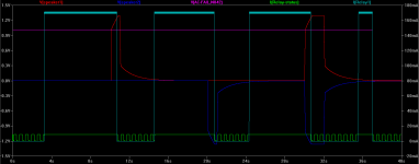
- Screenshot of operation with latch disabled to show every case that is covered
Attachments
I think that you need to use excellent upc1237 protection...this what you have designed is implement in upc1237 8-pin SIP case...without too much external components....also look at Silicon Chip Speaker Protection schematic...if you like discrete components without too much components..i posted for this two speaker protection PCB..so look here and see if this fill your requirements...
http://www.diyaudio.com/forums/solid-state/120614-loudspeaker-protection-circuit-2.html#post4844233
http://www.diyaudio.com/forums/solid-state/120614-loudspeaker-protection-circuit-2.html#post4844425
http://www.diyaudio.com/forums/solid-state/120614-loudspeaker-protection-circuit-2.html#post4844830
Also look at APEX NE555 speaker protection stereo module..it is working from 12VAC transformer...when i will have time i will design with 16-pin AVR speaker protection using Analog-To-Digital conversion for mV detection...LCD readout for digital volume potenciometer and AC-power off on amplifier off....
Thank you for all the information.
This schematic
http://www.diyaudio.com/forums/solid-state/120614-loudspeaker-protection-circuit-2.html#post4844425
is almost the same circuit wise but lacks the Schmitt trigger and is for a single channel only.
However, it confirms that this approach is used more often and can't be that bad.
I've seen all those uPC1237 designs.
Yes, this seems to be an interesting IC implementing some functions I need.
But I cannot find the part from a reputable distributor. It seems obsolete.
And I started to dislike integrated solutions for simple tasks some time ago but this is a long story.
The APEX circuit does DC sensing and probably turn on delay but has no AC loss detection.
I did not find the Silicon Chip circuit. Need to search harder.
Thank you again for pointing me to other solutions.
Why not do as the professionals do. Use a compressor that directly samples the voltage going to the loudspeaker that is pre programmed to start compression at a specific voltage, depending on chosen loudspeaker limits and shut down the output in case of DC. Build in a start up timer, shut down switching and there you have it, active protection.
Takes all the guess work out of protecting speakers.
Takes all the guess work out of protecting speakers.
Thank you for all the information.
This schematic
http://www.diyaudio.com/forums/solid-state/120614-loudspeaker-protection-circuit-2.html#post4844425
is almost the same circuit wise but lacks the Schmitt trigger and is for a single channel only.
However, it confirms that this approach is used more often and can't be that bad.
This SC circuit is for stereo...see schematic ( i draw PCB for mono version...but you could drive it to stereo PCB if you like)....yes it does not have Schmitt trigger but i think it is stable, fast and less parts that your design.
This schematic from SC goes up to MAX 70VDC, what is max simulated voltage for your protection?
Also astabile multivibrator in your schematic you can replace with NE555 or dual NE556 to replace astabile multivibrator (RELAY LED status) and DC detection (using two NPN that output is to connected to NE555 or NE556 schmit trigger detection circuit)...this means leass parts with 8pin DIL IC and smaller and compact PCB.
Why not do as the professionals do. Use a compressor that directly samples the voltage going to the loudspeaker that is pre programmed to start compression at a specific voltage, depending on chosen loudspeaker limits and shut down the output in case of DC. Build in a start up timer, shut down switching and there you have it, active protection.
Takes all the guess work out of protecting speakers.
I'm sure you are right.
Protecting speakers requires a concept that goes far beyond the scope of this topic here.
Do you have example schematics for such a compressor/limiter scheme?
BTW: I killed my tweeter with amplified start up noise from a preamp.
A kind of limiter maybe could have helped.
But the start up delay as well.
This SC circuit is for stereo...see schematic ( i draw PCB for mono version...but you could drive it to stereo PCB if you like)....yes it does not have Schmitt trigger but i think it is stable, fast and less parts that your design.
This schematic from SC goes up to MAX 70VDC, what is max simulated voltage for your protection?
Also astabile multivibrator in your schematic you can replace with NE555 or dual NE556 to replace astabile multivibrator (RELAY LED status) and DC detection (using two NPN that output is to connected to NE555 or NE556 schmit trigger detection circuit)...this means leass parts with 8pin DIL IC and smaller and compact PCB.
Now I see what you mean with "Silicon Chip" schematic.
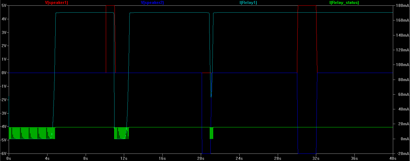
The Schmitt trigger is not absolutely necessary. But without things are a bit undefined. The relay is switched slowly and its status is not clearly defined. See attached plot of the original DIY Audio protection circuit. At 21s the relay is switched half off to get turned on again.
In my case the voltage going to the series regulator is round about 90 Volt. This is why I use a series regulator made up of discrete components.
The SC schematic you shown is rated for 20VDC.
Sure I can replace two transistors that work with almost any supply voltage with one or two ICs that cannot work with the 24V supply present and still require lots of passive components. But to me it does not make sense.
You're right - the PCB is going to be quite large.
I estimated 140mm by 100mm.
Attachments
BTW: I killed my tweeter with amplified start up noise from a preamp.
A kind of limiter maybe could have helped.
But the start up delay as well.
Sounds more like nasty oscillation than just noise.
How about muting the input of your amp while the speaker protection ist sill engaged ?
I killed my tweeter with amplified start up noise from a preamp
either (remember to) turn on/off preamp and power amp in the correct order, or fit the preamp outputs with muting devices.
Last edited:
The upc1237 is indeed a nice IC, but it is discontinued and this pretty much leaves getting NOS or fakes from eBay. Not really worth the risk.
To be honest you dont really need a linear regulator. You can usually run the detector part straight from the power amp's supplies. I favour a detector that works between the voltage rails - Rod Elliot's protection circuit does this, but I first learned of it from Arcam. I also dont see the need for two seperate detectors per channel.
Turn on delay really doesnt need to be any more complicated than an R-C based timing circuit.
There is not too much to these ckts. Pioneer used the same ckt for years. Stick with a good proven thing. Easy to make up even using discrete. it can be very small if you do it in smt. I liked their idea with the balanced bridge for current sense and O/C protection.
I have re-used the Hitachi HA12002 in the Sansui G-7500 mod. You get your -ve voltage from the 7.5VAC for the lamps.
Of course it can get better if you incorporate a mcu, then you can sequence events etc.
I hope you have looked over this thread
http://www.diyaudio.com/forums/solid-state/264313-how-build-21st-century-protection-board.html
Last edited:
that's only possible if the two channels are isolated.Can be used for my dual mono design without hard wiring ground of the two amps together.
That requires four secondary windings, or two sets of centre tapped windings.
The one that does the job
Hi Lee,
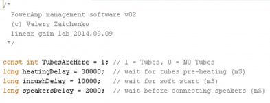
That means - most likely, you didn't look into our "21-st century control boards", just mentioned by Rick above")
Let me know if you will have questions.
Cheers,
Valery
But none work the way I need them to.
Hi Lee,
That means - most likely, you didn't look into our "21-st century control boards", just mentioned by Rick above
Let me know if you will have questions.
Cheers,
Valery
Attachments
I've seen all those uPC1237 designs.
Yes, this seems to be an interesting IC implementing some functions I need.
But I cannot find the part from a reputable distributor. It seems obsolete.
ProfusionPlc.com sells UTC (Unisonic Technologies Co.) semiconductors so I would regard that as a good sign, however I couldn't find the UPC1237 on their web page.
http://www.unisonic.com.tw/datasheet/UPC1237.pdf
Or you could go for assembled PCB's from AliExpress, here is one example I just found.
https://www.aliexpress.com/store/pr...peaker-protection-board/911703_731933186.html
Hi Everybody,
thank you so much for all the feedback.
Sorry for delayed reply.
I have a nasty cold right now and no progress with the project.
kct, citrix:
jaycee:
rsavas:
AndrewT:
vzaichenko:
maiko:
I'll update as soon as I recovered.
thank you so much for all the feedback.
Sorry for delayed reply.
I have a nasty cold right now and no progress with the project.
kct, citrix:
- Yes, my fault with the tweeter. Quite often it's just the user but equipment needs to be idiot proof, too.
- Thanks for the hint. I will add an interface for input / preamp muting relays.
jaycee:
- uPC1237 is not an option since it is discontinued.
- Having a linear regulator is nice. I can use the 24V supply for something else in the amp.
- I don't plan two separate detectors. Just one board for two channels. But those two channels need to be sensed separately.
rsavas:
- Thank you for hint to the proven designs and the link. I will research / read them.
AndrewT:
- Yes, I have two separate transformers.
vzaichenko:
- Thank you. I will read the thread.
maiko:
- Thank you. I've seen those designs on Alibaba and ebay. I wonder how they can sell those modules for less than the parts worth including free shipping. They may be okay for a small amp but mine is huge.
- I haven't found any relay that could interrupt a fault current (90V/???A) and think about solid stated relays now.
I'll update as soon as I recovered.
if you sense separately then you detect separately.......................
- I don't plan two separate detectors. Just one board for two channels. But those two channels need to be sensed separately.
That requires TWO detectors. Not a single detector with two inputs.
if you sense separately then you detect separately.
That requires TWO detectors. Not a single detector with two inputs.
Yes, you are right.
Two detectors are necessary.
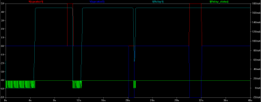
The reason for this is that for the case one amp output develops a positive DC voltage and the other one a negative and you only have one detector, the two opposing voltages cancel out.
See this simulation with one detector only:
At t=30 seconds, this case happens and it is not detected by the circuit. Both loudspeakers get roasted.
That's why you make the dropping resistors of a different value, so that they don't exactly cancel out. I saw this solution a few decades ago, but almost no designer since has adopted it. But this does reduce the sensitvity of one channel with respect to the other.
Sensitvity is not an issue if both channels, or one channel, fails to rail voltage.
Sensitvity is not an issue if both channels, or one channel, fails to rail voltage.
- Home
- Amplifiers
- Solid State
- Improved speaker protection circuit