Here is my solution for the protection. Contains on delay, DC, and thermal protection, and fan speed controll, using 2xLM339, and some small signal transistors.
Sajti
HI
can you share PCB and Schematic for this protection?
thank you
Schematic.
I have the PCB in Eagle, or gerbers.
Sajti
OK
thank you
what about short circuit ?
have this too?
OK
thank you
what about short circuit ?
have this too?
The short circuit protection is V/I limiter built within the amplifier.
Sajti
If you want to disconnect the speakers immediately upon loss of AC and you are using DC coil speaker relays, one way to do this is employs an additional AC coil (120VAC) relay that will either connect the speaker relay coils to DC power, or short them. Shorting is not to ground, it is making a short circuit across the coil. The speaker relays immediately open without having to wait for a linear power supply to drain down to a couple of volts (min relay coil operating voltage). I have used this approach in a couple of projects and it worked well to limit turn off noises from my amps and other circuitry.
Last edited:
I made a little progress in the meantime.
I tried to make the series regulator more robust by adding some current limiter but was not satisfied with the result.
So I decided to use an integrated solution instead - the TL783. This has full protection built in and saves a lot of board space. If I had found this part earlier I could have saved a lot of time.
The remaining circuit stayed more or less the same.
I used the freed up board space for some heat sinks. The SSR might get a little warm under extreme conditions plus the heat sinks provide some mechanical support to the expensive MOSFETs.
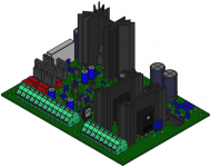
This is how the board may look like:

I tried to make the series regulator more robust by adding some current limiter but was not satisfied with the result.
So I decided to use an integrated solution instead - the TL783. This has full protection built in and saves a lot of board space. If I had found this part earlier I could have saved a lot of time.
The remaining circuit stayed more or less the same.
I used the freed up board space for some heat sinks. The SSR might get a little warm under extreme conditions plus the heat sinks provide some mechanical support to the expensive MOSFETs.
This is how the board may look like:
Attachments
Schematic.
I have the PCB in Eagle, or gerbers.
Sajti
Hello friend,
Will you be so kind and send me gerber files on: anddrej(@)gmail.com
If you want to disconnect the speakers immediately upon loss of AC and you are using DC coil speaker relays, one way to do this is employs an additional AC coil (120VAC) relay that will either connect the speaker relay coils to DC power, or short them. Shorting is not to ground, it is making a short circuit across the coil.
If you want a relay to open quickly you must interrupt the current in the coil fast, not short the coil. This means using a high-voltage snubber circuit (the higher the inductive kick voltage, the more rapidly the magnetic field subsides in the relay, allowing the contacts to release).
If you short a relay coil while its energized the current ramps down much more slowly as only the resistance of the coil is available to dissipate energy.
The time-constant of a shorted relay coil is L/R, of an interrupted coil is L/kR where k is the ratio of inductive kick voltage to operating voltage.
So for instance a 12V 1H 40 ohm coil has a time constant of 25ms shorted,
whereas if interrupted with a 100V MOV to snub it the time constant is about 3ms.
If you are used to capacitors, where shorting creates a dramatic and rapid change of state, you need to realize that interrupting the current to a coil is the dramatic/rapid thing to do to a coil, a shorted coil is in the resting state like an open capacitor. current is to coils as voltage is to caps.(+)
But inductors have significant series resistance meaning their current self-discharges when shorted on a timescale of around a second(*), whereas the low leakage of capacitors means their voltage self-discharges when open-circuit on a timescale of days or more.
(*) You have to use superconducting coils to approach (exceed) the time constant of capacitors.
(+) the differential equations show this nicely (even if you don't understand them):
I dt = C dV
V dt = L dI
Last edited:
Hello friend,
Will you be so kind and send me gerber files on: anddrej(@)gmail.com
Guess not
Dear DIY Audio Community,
<snip>
Hi Lee,
Great circuit. I am late to this conversation but am wondering if you have any up to date design changes and/or PCBs for this circuit that you would consider selling ?
Thanks
Hi,
believe it or not, I'm still working at this from time to time. Most of the time, I'm not working at this project though. This is why it is still not finished. However, I have PCBs now waiting for assembly.
Meanwhile the design has changed countless times. This is because I changed the basic concept. A good concept to start with is foremost important.
The concept I ended up with finally is that each channel has its own circuit that is completely independent from the other channel. Everything is galvanically isolated, making it suitable for dual mono applications with separate supplies and to avoid any ground related issues. The amplifiers supply rails can be used, but the circuit can run from any supply.
The power supply was excluded and so was the mains voltage failure detection. The "shutdown" input is for instant speaker off in case the power supply reports mains voltage failure.
The circuit should work with a very broad range of supply voltage, maybe from 12V up to roughly 100V. Upper limit should be transistor power dissipation and Vce breakdown limited.
I like to reduce the cable mess inside amplifiers and I don't really like binding posts for the speaker connection so I put Speakon connectors on the board.
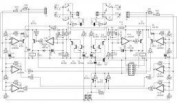
The schematic became even more complex of course. I don't really mind complexity as long as it has some benefit.
I don't provide Gerbers for any of my projects, but you may have PCBs if you like. But first, let me test whether it works.
Please find attached some screenshots how the assembly and schematic blocks look like now.
believe it or not, I'm still working at this from time to time. Most of the time, I'm not working at this project though. This is why it is still not finished. However, I have PCBs now waiting for assembly.
Meanwhile the design has changed countless times. This is because I changed the basic concept. A good concept to start with is foremost important.
The concept I ended up with finally is that each channel has its own circuit that is completely independent from the other channel. Everything is galvanically isolated, making it suitable for dual mono applications with separate supplies and to avoid any ground related issues. The amplifiers supply rails can be used, but the circuit can run from any supply.
The power supply was excluded and so was the mains voltage failure detection. The "shutdown" input is for instant speaker off in case the power supply reports mains voltage failure.
The circuit should work with a very broad range of supply voltage, maybe from 12V up to roughly 100V. Upper limit should be transistor power dissipation and Vce breakdown limited.
I like to reduce the cable mess inside amplifiers and I don't really like binding posts for the speaker connection so I put Speakon connectors on the board.
The schematic became even more complex of course. I don't really mind complexity as long as it has some benefit.
I don't provide Gerbers for any of my projects, but you may have PCBs if you like. But first, let me test whether it works.
Please find attached some screenshots how the assembly and schematic blocks look like now.
Attachments
-
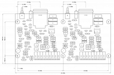 modular_amplifier_speaker_protection_V01_assembly_thumb.png138 KB · Views: 458
 -
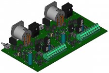 modular_amplifier_speaker_protection_V01_assembly_3d_01.jpg140.2 KB · Views: 463
 -
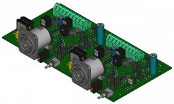 modular_amplifier_speaker_protection_V01_assembly_3d_02.jpg129.8 KB · Views: 455
 -
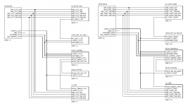 modular_amplifier_speaker_protection_V01_schematic_block.png83.2 KB · Views: 451
I will explain the schematic page by page.
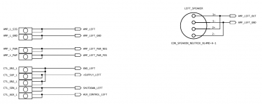
This page is just the interface.
The module only needs a power supply for the control circuitry plus the amplifier output and ground connected in order to work.
Amplifier power supply rails are optional. Note that the control power supply is galvanically isolated from the amplifier.
Pulling "shutdown" to ground disconnects the speaker.
"Aux_control" is an open collector output that can be used to switch something together with the speaker. Ground reference is the control supply.
Attachments
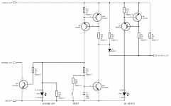
Page 3 - DC detection
This is where the circuitry becomes interesting:
The amplifier signal output is low pass filtered by R1 and C1, voltage limited by D1 and D2 and then activates the switches Q1 for positive DC and Q2 for negative DC.
Q1 and Q2 control the current sources that feed the opto-relays.
DC detection threshold is roughly 2V.
There are more sophisticated approaches available with lower detection threshold and faster response time. This one should be good enough to protect a full-range speaker that has a passive crossover inside.
The supplies for the opto-relays are generated from the amplifier output. This is what D9 and D10 are for.
Amplifier supplies can be connected optionally. In that case, D9 and D10 must not be installed.
D3 and D4 are not really required if D1 and D2 have lower breakdown voltage. The point is that Q1 and Q2 need to be protected from high reverse voltage at the base.
Attachments
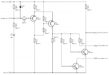
Page 4 - latch off on DC event
Once one of the opto-relays are engaged, two current sources are powered by pulling the node "DC_FAULT" to ground. One CCS lights up the indicator LED. The other one charges C3 and latches itself on via Q11. Another LED indicator shows that the latch activated. S1 resets the latch. Also, the shutdown is initiated, which turns off the speaker solid state relays.
Note that I use those switched CCS everywhere instead of a single transistor. This makes the circuitry supply voltage independent. Complexity is increased dramatically, but those parts are super low cost so I don't mind.
Attachments
Page 5 - delay control
Basically this is just a Schmidt trigger.
After some time, the loudspeaker SSR is engaged and shut off instantly once "shutdown" is pulled to ground.
Shutdown is controlled by the latch, which is triggered in case of DC at the amp output and can be controlled by the power supply in case of mains voltage loss.
Attachments
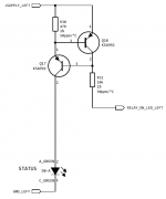
Page 6 - Relay status indicator
This is really nothing special. I dropped the astable multivibrator circuit although I like it and it provides better status messages. The reason was that I ran out of PCB real estate (wonder why) and it only works well at low supply voltage. In case the module is powered with like 100VDC, I found it difficult to deal with high reverse voltage at the transistors bases.
This is really nothing special. I dropped the astable multivibrator circuit although I like it and it provides better status messages. The reason was that I ran out of PCB real estate (wonder why) and it only works well at low supply voltage. In case the module is powered with like 100VDC, I found it difficult to deal with high reverse voltage at the transistors bases.
Attachments
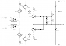
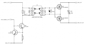
Page 7 - loudspeaker solid state relay
This is probably the single most expensive page - expensive photovoltaic gate drivers, expensive MOSFETs. Dependent on use case, cheaper MOSFETs are an option.
I guess there is not much to explain here.
This is probably the single most expensive page - expensive photovoltaic gate drivers, expensive MOSFETs. Dependent on use case, cheaper MOSFETs are an option.
I guess there is not much to explain here.
Attachments
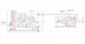
i have a question- I never had any seriuos issues with any of my amps without any protection for 20years. pass labs is very reliable amps. now my other amplifiers shematic is diferent, only two trasitors runing at 66v and doing it in class a. if speakers are not connected it starts oscilate and blow speakers. I have implemented DPTH relays (when system starting it takes 5-7 seconds ,so output from amp is not delivered to speakers dummy load of 5.6ohms 50w on amp, when relay activated 5.6ohm load disconected)
my problem is that I need protection from DC when something goes wrong, I don’t mind amp blow ,its eas to repair, but I really concerned about expensive speaker drivers. and I have clever protection its microcontroler operated combined protection with fan coolings temperature tresholds,etc in event of any failure microcontroler sends signal and relays are cut. the problem is HOW to connect this protection to other amplifer(with diferent schematics- https://www.diyaudio.com/forums/dig...put-1704-dac-paraleling-dacs.html#post6522779)
I missing only one point for conection marked with arrow . unless protection parts are integated deeper in the amp(larger square) I need protection and amp guys chime in , because I do not understand this amp (darlington transistors) and protection. thanks a million
Attachments
- Home
- Amplifiers
- Solid State
- Improved speaker protection circuit