Also it is too optimistic claim for completely right amplifier it is just an idea to calculate as much as possible accurate circuit.
All parameters should be under acceptable limits without output inductor. Unconditional stability, low enough distortions, fast enough slew, good driving capabilities, reasonable power, and highest possible simplicity.
Analysing was made by LTspice tool and Cordell models but not yet tried in real world so I think here is right place to make this final step.
For sure great specialist around this forum can help make the circuit alive, and advance it as many other projects.
So, some resoults are attached under, waiting for responce")
All parameters should be under acceptable limits without output inductor. Unconditional stability, low enough distortions, fast enough slew, good driving capabilities, reasonable power, and highest possible simplicity.
Analysing was made by LTspice tool and Cordell models but not yet tried in real world so I think here is right place to make this final step.
For sure great specialist around this forum can help make the circuit alive, and advance it as many other projects.
So, some resoults are attached under, waiting for responce
Attachments
-
Comri_ref_sch.pdf41.1 KB · Views: 71
-
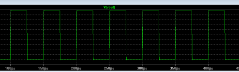 Square_20kHz.png7.7 KB · Views: 64
 -
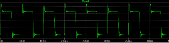 Square_20kHz_1.1uF.png9.4 KB · Views: 59
 -
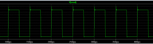 Square_20kHz_0.1uF.png7.4 KB · Views: 59
 -
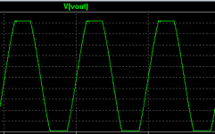 Clip_20k_0.1u.png4.6 KB · Views: 167
 -
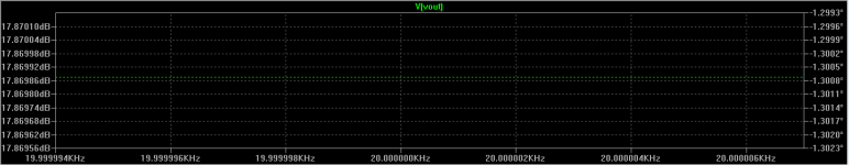
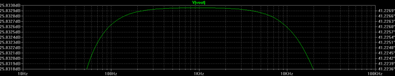
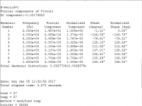 THD_20k.png20.3 KB · Views: 175
 -
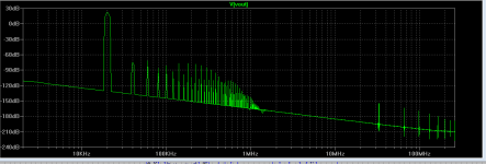 FFT_20k.png29.1 KB · Views: 177
 -
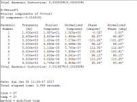 THD_1k.png20.3 KB · Views: 174
 -
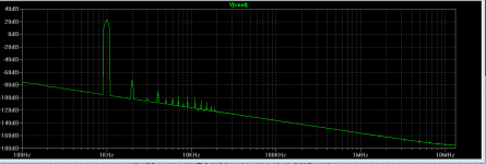 FFT_1k.png25.2 KB · Views: 177
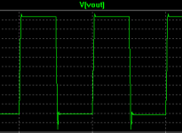
Overshoot and ringing look bad pics 6 & 7. What was the load?
pic 6 => 8ohm II 100nF
pic 7 => 8ohm II 1uF
Yes, not perfect, but in order to preserve slew >25V/uS and THD < 0.003% is worth compromise. Of course, ringing is eliminated when output inductor is used, and overshot is removed until 1uF load also.
I compare it with proved designs like legendary P3A, and it is not too bad when 3x slew is taken in account. Attached is P3A under same conditions. Overshot is still there, as capacitance models apply zero ohmic load. In reality there is always some ohmic resistance.
Attachments

It might be worth including some spaces and pads for extra compensation components before you create your PCB layout.
Then when you get the real amplifier running you have some opportunity to tune out the overshoot and get adequate phase and gain margins.
I have some commercial amplifier PCBs and they include extra components tagged on in various locations. This is probably because these professionally designed PCBs did not include sufficient compensation at the initial design stage and needed more work when the real amplifier was tested into slightly reactive loads.
If you read JLH, you will see he refers to over shoot and how to remove it (but only just enough) to get improved sound. One of his techniques was an adjustable R in series with the input inclusive compensation capacitor to tune out the overshoot.
That is what I do with C14 on attached schematic. It should be omitted if amp works without. Also values can be adjusted when prototype is done. So, all we need is enthusiastic builder willing for experimentation
Attachments
- Status
- This old topic is closed. If you want to reopen this topic, contact a moderator using the "Report Post" button.
- Home
- Amplifiers
- Solid State
- Comri_completely_right