Battling on old Philips 210WPC amp...my buddy blew it up, and it required an output bjt or two, a few drivers and resistors, and the pre-drivers to put it right. It also uses an opamp (4558) at the input for a subsonic filter. I replaced the 4558 with a NE5532, gave the 5532 a decent bypass, and fired it up.
Once running, and while looking at the signal to the main amp with a scope, I saw some nasty oscillation (about 3MHz or so, amplitude of about 1V P-P). Figured the layout was just not right for a 5532, so put the 4558 back in. STILL oscillating. What's more, I see that ALL the voltage supplies in the amp show this oscillation riding on the rails (several zener regulated +/-15V, a standby +12V, and another +14V for the front LED's).
OK...so I completely remove the opamp from the circuit (socketed now), thinking there is a broken trace or some such contributing to the problem. Even with the opamp completely out of the amp, the rails show the oscillation.
I note that...with a scope probe on the chassis, I see nothing odd. However, at the 'common' of the big filter caps, I see oscillation. Very odd, as they are tied to the chassis a few inches away. An ohmeter reading shows a short, as it should. It's a good hefty wire (about 12ga) and connection is well soldered.
For the hell of it, I take a .01µf stacked film cap and 'short' the common of the filter cap to the chassis. Oscillation disappears. I don't know why, but I also took the .01µf cap and 'shorted' across one of the diodes of the big diode bridge for the main high-current supply. Oscillation almost disappears. I tried adding a cap across all of the bridge (I guess these are called 'snubber caps' when used like this??), and the oscillation is totally vanished.
The amp uses a quite large transformer with a single high-current winding common to both channels, but has a separate diode bridge for each channel. Doesn't matter which bridge I add the snubber caps to (if that's what they are called), but once added oscillation is completely gone.
Amp seems to run fine now, but I can't help but wonder how/why the oscillation started...was it always there? Has something gone bad that is not-so-obvious starting the oscillation? Why in the world would an unregulated supply begin oscillating in the first place? Do bridge diodes really create that much high-frequency trash?
Turns out that adding the caps to the bridge only took care of the oscillation at idle. Once a signal is added, the output waveform gets the 'fuzzies' on the negative half of the wave.
The driver boards are connected with a female plastic connector that pushes onto male pins on the chassis. By adding .01µf caps to the ground wires running to the driver board, almost all the oscillation is gone.
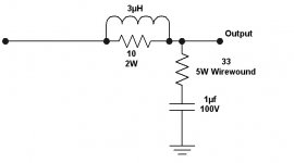
However, I noticed that the most improvement came when adding the .01µf cap to the ground for the Zobel filter. I suspect that this filter, which consists of what looks like a cheap cap and a wirewound resistor, is the problem now. When the speaker switch is set to disconnect any load, there is no oscillation at all. With the dummy load connected, there is the small bit of oscillation on the negative peak of the waveform. Since the oscillation, small though it may be, disappears with the load disconnected, I'd like to replace the filter with some better parts and see what happens.
Below is a pic of how it is set up now. I thought it odd that the filter is on the far side of the inductor/resistor combination. Is that why the values are so large (33 ohm and 1µf..), or is there any reason why I can't use a more standard value of like 5-10 ohms and a 0.1µf cap?
The driver boards are connected with a female plastic connector that pushes onto male pins on the chassis. By adding .01µf caps to the ground wires running to the driver board, almost all the oscillation is gone.
However, I noticed that the most improvement came when adding the .01µf cap to the ground for the Zobel filter. I suspect that this filter, which consists of what looks like a cheap cap and a wirewound resistor, is the problem now. When the speaker switch is set to disconnect any load, there is no oscillation at all. With the dummy load connected, there is the small bit of oscillation on the negative peak of the waveform. Since the oscillation, small though it may be, disappears with the load disconnected, I'd like to replace the filter with some better parts and see what happens.
Below is a pic of how it is set up now. I thought it odd that the filter is on the far side of the inductor/resistor combination. Is that why the values are so large (33 ohm and 1µf..), or is there any reason why I can't use a more standard value of like 5-10 ohms and a 0.1µf cap?
Attachments
If you can, I'd put the zobel 'before' the L||R thingie, using a good quality 0.1uf cap & 10R3W. Also try to 'bypass' the power rails with .1uf as close to the output devices as possible and I'd add a tinyl value cap (68pf or so) across the amp's input (signal+ to signal ground.)
Thank you very much for the reply.
It won't be easy to move the filter, but it can be done. I certainly don't look forward to pulling those driver boards out yet again, but I got no choice.
The amp input has a 100pf cap already between input and ground. Signal at the amp input stage looks quite nice, and even at the output it looks very good until power out hits about 100W or so. Then the fuzzies start to show up on the negative peaks.
I'll see if I can't get the parts I need.
If anyone ever tries to give you a Philips amp, politely decline.
Interesting problem. I can only comment with generic thoughts that may or may not help.
You need gain and feedback for an oscillation to sustain itself. Zener-transistor regulated power supplies don't have that, so the source of oscillation must be somewhere in the amp.
My first technician's job was at a power supply company. When measuring the output ripple it was common to see high frequency hiss on a 'scope. The chief engineer said it wasn't "real", and proved it this way: short out the 'scope probe and touch it to the circuit. If the noise remains it's an anomoly in the measurement system, not part of the circuit. We usually put the 'scope on bandwith limit to ignore such nonsense.
These 3Mhz thing dependent on output load and instantaneous voltage look much like output stage oscillations due to unstability [feedback applied at frequencies where loop phase shift is 180º or greater]
You should study the amplifier circuit. Dry small/mediul electrolytics or faulty compensation capacitors may cause this problem. Fake, low quality or slower than original transistors may also cause it. Finally, it may be a design flaw of the original amplifier and in this case you should think about increasing closed loop gain or increasing compensation in order to make it stable
Drawing an schematic and posting it may help to identify what components could cause the unstability
You work would be finished when the amplifier could drive a 1uF capacitor direcly connected to the output, entering into clipping and without apreciable oscillations
You should not let the amplifier oscillate since this oscillation markedly increases THD and IMD and there is some risk of blowing output devices due to cross-conduction
maylar...
I certainly considered this, but how can I not trust what I see with the scope? In any case, it appears that adding a slew of .01µf bypass caps from the chassis to several of the internal ground connections has improved the situation markedly.
Eva...
Both channels exhibit exactly the same behavior, so I think a failed cap is unlikely. I believe this is a design issue...
The 3MHz oscillation is gone. What I have now I call 'oscillation' for lack of a better word. It actually is more of 'mild instability' on the negative half of the wave, slightly blurring the waveform and becoming more pronounced as the wave approaches its negative peak. The positive half of the waveform looks just fine. Moreover, the phenomenon I describe does not present itself until...
1) A load is connected, and
2) Power output approaches 100W
With no load the wave is clean as can be. This is why I feel it may lie with the poorly chosen wirewound resistor for the Zobel filter. Any other thoughts on moving the filter before the R||L output coil? Or the size of the filter components?
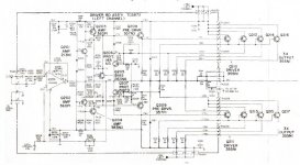
I'd scan the schematic, but sections of it are shaded, and may be tough to read. Still, I'll see what I can do.
I certainly considered this, but how can I not trust what I see with the scope? In any case, it appears that adding a slew of .01µf bypass caps from the chassis to several of the internal ground connections has improved the situation markedly.
Eva...
Both channels exhibit exactly the same behavior, so I think a failed cap is unlikely. I believe this is a design issue...
The 3MHz oscillation is gone. What I have now I call 'oscillation' for lack of a better word. It actually is more of 'mild instability' on the negative half of the wave, slightly blurring the waveform and becoming more pronounced as the wave approaches its negative peak. The positive half of the waveform looks just fine. Moreover, the phenomenon I describe does not present itself until...
1) A load is connected, and
2) Power output approaches 100W
With no load the wave is clean as can be. This is why I feel it may lie with the poorly chosen wirewound resistor for the Zobel filter. Any other thoughts on moving the filter before the R||L output coil? Or the size of the filter components?
I'd scan the schematic, but sections of it are shaded, and may be tough to read. Still, I'll see what I can do.
it required an output bjt or two, a few drivers and resistors, and the pre-drivers to put it right.

What exactly did you change?
Wow...
Well, this thing was fairly smoked. Q210 (driver) was shorted, as well as Q212 IIRC. Anyway, since I had no idea what these '355NI' devices are (although they were labled Toshiba), I moved Q211 to where Q212 was, and replaced the drivers with 2SD555's.
The pre-drivers were also toast, and replaced with 2SA1535's and 2SC3944A's.
All of the .47 ohm emitter resistors were open, and were replaced, as well the 10 ohm 2W resistors for the drivers.
Bias transistor was shorted, and replaced with a 2SD756A.
D206 in the protection leg was shorted, and replaced with a 1N4148.
Attachments

OK..here I am talking to myself again...
I've got some 5.1 ohm 3W resistors, and some nice .1µf 400V metal polypro caps. Would the 5.1 ohm resistor be too small for the Zobel? I've seen amps with Zobel resistors as low as 4.7 ohm with the .1µf cap, so seems like a 5.1 should be OK...
I have no 10 ohm resistors, but some are on the way.
I've got some 5.1 ohm 3W resistors, and some nice .1µf 400V metal polypro caps. Would the 5.1 ohm resistor be too small for the Zobel? I've seen amps with Zobel resistors as low as 4.7 ohm with the .1µf cap, so seems like a 5.1 should be OK...
I have no 10 ohm resistors, but some are on the way.
This 'fuzz' in the waveform is transient oscillation that only happens with certain Vce/Ic conditions that make the transistors not fast enough to have less than 180º total loop phase shift up to frequencies where there is no longer feedback
I've also seen this problem when replacing 'equivalent' transistors in quasi-complimentary output stages or even when replacing VAS transistors of the same model but from different brand and with different capacitances
The problem obviously comes from the transistors you have replaced
The drivers you've used are probably slower or have higher capacitances than the old transistors. Try to decrease the value of the 100ohm 0.5W resistors from the base of the drivers to the output and the negative supply respectively, this will 'speed up' the circuit again [try 47 ohm]. Take into account that reducing the value of these resistors will increase the idle current through the predrivers and now they may require heatsinking. Try also reducing the value of the 10ohm 2W resistors connected to the bases of the output devices
Increasing the value of the 22pF miller capacitors from B to C of the voltage amplifier transistors may also help eliminating the oscillation but this will actually reduce the gain-bandwith product of the amplifier and its slew rate
EDIT : Reducing only the base resistors of the drivers may not be a good idea since their gain is already reduced to 10. Try instead to place a 47 ohm resistor from B to E of the drivers. Another option is to reduce both the 100 ohm and the 10 ohm resistors by the same proportion, maybe to 47 ohms and 4.7 ohms. 0.47 ohm output emitter resistors may be also reduced to 0.22 ohms. And another option is just to use faster driver transistors, ie: Motorola MJE15030 or MJE15032 depending on voltage requirements, but adapting them to the TO-3 mounting place may be difficult
Well, if it is a matter of transistor speed, then the only one to blame would be the 2SD555 that I used for the driver...the other devices are fairly high bandwidth units. I can't find much info on the D555, but at least one site claims it's ft=7MHz. which would not be real slow...
For all I know, the problem has been there since the amp left the factory years ago, so I can't say that it is a new thing, only that it is there now.
Could you explain what the 47 ohm resistor on the B-E of the driver would do?
Also, your 'no comment' on the Zobel would seem to indicate you think that this is the wrong approach...
At high frequencies, bipolar transistors work like MOS deivces : They need positive base currents to turn on and *negative* base currents to turn off. Removing base current is simply not enough to turn off a bipolar transistor since the base-emitter junction is charged like a capacitor and has to be actively discharged to provide fast turn-off [internal discharge process is very slow]
Fast small signal transistors need small negative currents, large power transistors need large negative currents to turn off fast enough
The 47 ohm resistor from B to E is an attempt to provide higher turn-off current and speed-up the circuit in order to increase open loop phase margin and eliminate the unstability caused by excesive phase lag
The total bandwith of the circuit is not defined by te turn-on speeds of the transistors but by the minimum between both turn-on and turn-off speeds
I recommended MJE15030/15032 because they are inexpensive TO-220 devices, and I tried MJE15030 in a switching circuit and it showed fast turn-off [minimum current tail] even with small negative base currents [FT > 30Mhz]
The RC network on the output is ok as long as it presents a low resistive impedance at high frequencies. The circuit needs this resistive load in order to have a fixed bandwith independent of what you connect on the output binding posts. A simple 4.7 ohm 1W or 2W resistor and a ceramic or film 100nF capacitor is more than enough to accomplish the task.
The reason to use a power resistor is to prevent it from overheating and opening in case of slight RF oscillation, since without the RC network the oscillation may get enough amplitude to cause cross-conduction on the output stage and blow output devices. In normal working conditions, a 0.25W resistor works fine [as long as you don't amplify full amplitude high frequency signals] since there is no RF to heat it and the 100nF capacitor shows 80 ohms at 20Khz
About measuring a >3Mhz oscillation :
At 3Mhz, wires no longer show low impedances, actually everything works like an inductor or an antenna at these frequencies. dI/dt in each wire induces proportional dV/dt on the rest of wires so it's normal to see 3Mhz crap everywhere, specially in audio amplifiers since the layout is not designed to handle RF
The probe of the oscilloscope and its wire also work as antennas and pick up 3Mhz crap even without connecting them to the circuit, just connect a loop of wire between the tip and ground of the probe and slide it near anything oscillating
Also, even if the oscilloscope is earthed and the amplifier's case is also earthed, there will be an AC potential between the ground of the amplifier and the ground of the oscilloscope [wiring is inductive] and an AC ground loop will be created. I usually place a common-mode filter on the wires of the probes to attenuate the common mode signal
I experiment more with SMPS than with audio amplifiers, and for higher frequencies things get much worse
Look at the picture of common-mode filtering :
Attachments
Eva, you are most kind to help out...your suggestions are appreciated. I do have 47 ohm resistors here, but they are only 1/4W...do they need to be larger?
Also, looking at the prints. C213, the 470pf cap on the B-C of Q209 seems large. That cap needs to charge to pull the signal down. What is the possibility that this cap is too large and causing problems?
lucpes suggested moving the Zobel so that it is located 'before' the R||L output filter. Is that worthwhile? If not, I will simply replace the 33 ohm resistor with a 5.1 ohm, and the 1µf cap with a .1µf cap.
Thank you again... I am indebted...
47 ohm 1/4W is more than enough since Vbe rarely will reach 1V
If the oscillation is reduced with 47 ohms, try to put two 47 ohm resistors in paralell, this may eliminate it
You may also try to reduce the value of the 470pF capacitor to 330pF or 220pF but the oscillation may increase in amplitude
I recommend you use a burst tone generator program [for example SpectraRTA] to generate 20Khz periodic tone bursts [1-10% duty cycle] using the sound card. It's a great method for carefully testing amplifier stability with different loads, different levels and at clipping threshold without the need of heavy power resistors as a test load and huge heatsinks for the amplifier
[With 1% duty cycle you may use a 2W resistor to test the stability of a 200W amplifier]
If you have 5.1 ohm resistors, place one in paralell with the inductor and other in series with the 100nF capacitor. Moving the coil and its resistor to the output binding posts [after the RC network] is optional but take into account that this coil produces a magnetic field proportional to speaker dI/dt and thus it will be better to have it far away from small signal circuits [Leave the 10ohm resistor in paralell with the inductor if you move them to the binding posts]
There's always a downside...so what's the downside of adding the resistors to the B-E of the drivers?
(I will try this tonight....and since relocating the output R||L filter or the Zobel is difficult (but not impossible) I will simply replace the 33 ohm resistor with a 5.1 ohm, and the cap with a good quality .1µf and hope for improvement)
(I will try this tonight....and since relocating the output R||L filter or the Zobel is difficult (but not impossible) I will simply replace the 33 ohm resistor with a 5.1 ohm, and the cap with a good quality .1µf and hope for improvement)
.....other projects have gotten in the way, and now 've got to go to St. Louis for two days.
Looks like I'll be waiting and installing the 47 ohm resistors and the reworked Zobel at the same time once I return.
Eva, thank you... I'll post once I get back and have a chance to put the parts in...
Looks like I'll be waiting and installing the 47 ohm resistors and the reworked Zobel at the same time once I return.
Eva, thank you... I'll post once I get back and have a chance to put the parts in...
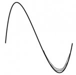
Before I take off, wanted to post a small (but bad..) drawing of what I see. In the drawing, the grunge on the negative wave is a little exaggerated, but wanted to give a general idea of what I see.
Perfect wave with no load, odd negative waveform with a load at high (90W+) output.
Perfect wave with no load, odd negative waveform with a load at high (90W+) output.
Attachments
- Status
- This old topic is closed. If you want to reopen this topic, contact a moderator using the "Report Post" button.
- Home
- Amplifiers
- Solid State
- Oscillating Power Supply....WTH?