I've got a pretty rare Sony TAN-8250 here that needs some love, but in looking at the schematic I see a style of regulator that I've not seen before.
Full schematic is here if you are interested.
Sony makes mention of adjusting this regulator for +/-65V when under a 50W load (is not clear in the manual whether they mean one channel under a 50W load, or both).
In any case, was wondering if anyone here might have some insight into what Sony is doing here and how this regulator works. Every time I think I have it figured out, I see something else that doesn't make sense. I mean, they are certainly using it to counter the voltage droop when under load, but the sensing mechanism is a bit fuzzy. With the additional power rails, I guess this is a Class H amp? Or maybe not, since 'H' is supposed to monitor the input, and this only appears to track the capacitor voltage.
I'd love it if someone more knowledgeable would chime in.
Last edited:
An odd way to go about it indeed. SCR based regulators are generally used for AC regulation in industrial equipment. The fact that the smoothing caps are located after the regulator would suggest they are controlling the pulsed DC from the rectifiers to determine the amount of charge time on them. Quite a complicated design overall.
There doesn't appear to be any sensing mechanism to switch voltages on the fly. Notice the sensing resistor string only monitors the + rail. This is a switchable stereo/mono and is rated 500 watts in mono. The half wave rectified tap supplies a low current 67V for the amp until the rail sags a certain amount at which time the scr's are turned on to supply charge to the reservoir caps until it reaches the 67 volt mark again. A scheme to reduce power consumption and heat.
Here's the original japanese desciption/specs, translated of course https://translate.google.com/transl....jp/SONY-ESPRIT/amp/tan-8250.html&prev=search
Here's the original japanese desciption/specs, translated of course https://translate.google.com/transl....jp/SONY-ESPRIT/amp/tan-8250.html&prev=search
Last edited:
Yes, that's why you have to produce minimum 50W before adjusting the voltage.Only the positive side is monitored, the negative side is copying the positive.There doesn't appear to be any sensing mechanism to switch voltages on the fly. Notice the sensing resistor string only monitors the + rail. This is a switchable stereo/mono and is rated 500 watts in mono. The half wave rectified tap supplies a low current 67V for the amp until the rail sags a certain amount at which time the scr's are turned on to supply charge to the reservoir caps until it reaches the 67 volt mark again. A scheme to reduce power consumption and heat.
Mona
There doesn't appear to be any sensing mechanism to switch voltages on the fly. Notice the sensing resistor string only monitors the + rail. This is a switchable stereo/mono and is rated 500 watts in mono. The half wave rectified tap supplies a low current 67V for the amp until the rail sags a certain amount at which time the scr's are turned on to supply charge to the reservoir caps until it reaches the 67 volt mark again. A scheme to reduce power consumption and heat.
Here's the original japanese desciption/specs, translated of course https://translate.google.com/transl....jp/SONY-ESPRIT/amp/tan-8250.html&prev=search
Good analysis.
Jan
For some reason that PSU reminds me of the RBM (Rank Bush Murphy) A823 Television circa 1970's.
Diode in series with the mains, then the SCR reg followed by a reservoir cap. 200 volts (regulated) DC of non isolated umpty scary stuff... don't try that at home.
It seems an odd choice for a high quality audio component as its very inefficient being half wave, and also consequently generates lots of 'half wave ripple'.
Diode in series with the mains, then the SCR reg followed by a reservoir cap. 200 volts (regulated) DC of non isolated umpty
scary stuff... don't try that at home.It seems an odd choice for a high quality audio component as its very inefficient being half wave, and also consequently generates lots of 'half wave ripple'.
Choke helps in that regard. Physically, it's nearly as large as the power transformer.It seems an odd choice for a high quality audio component as its very inefficient being half wave, and also consequently generates lots of 'half wave ripple'.
1975. It'd be hard to find something older using a scheme anything like this.Could be the original class H.
Yes, this is a fairly standard secondary side SCR regulator. Other attempts were made at this, usually on the primary side (most notably Yamaha CA-x60 series).
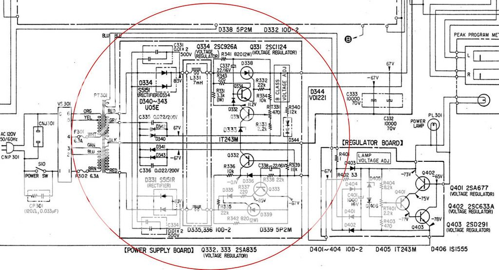
The point is to regulate the main power rails without significant heat loss. The half-wave rectifier part is enough to supply quiescent current, but the main power is supplied through the SCRs. The reason for the higher secondary voltage is some loss of voltage in the series inductors. These are actually filters and current limiters which prevent abrupt inrush currents once the SCRs are switched on, this also rounds out the rectified voltage removing a lot of high order harmonics from the rectified current, making the supply quieter. It's a form of phase regulation where there is a delay between SCR turn-on and the rectified waveform - the closer to zero crossing the SCR fires, the higher the output voltage. Note: this is NOT a half-wave supply, each side has two diodes from a center-tapped transformer. So, it's a series regulator for the main amp power supply. The most probable reason why it says 'class B supply' is due to some SOny nomenclature, where they call the output stage 'the class B stage' which it mostly is, because they call the input and first driver stages 'class A stages' which they are. So, it does not switch supply voltage in dependence of the output level, it's a classical amp with regulated power rails.
How does it work? Mostly the same as a typical regulator of that topology except the actual regulating element is not linear. It's easy to see on the positive side of the regulator. Q331 compares the output through a resistive divider to reference D333. If the output is higher, it's collector will pull down the drive to Q334 that comes through R331 normally, and turns on Q334 through D332. The 'phase regulation' comes in play by the resistance of R331 and C337 forming a time constant. C337 is charged by virtue of one side being the output of the regulator, which is always lower in voltage than the input. C337 will have to charge to at least the voltage drop of the diode D332 plus Vbe of Q334 plus firing voltage of the SCR, at which point the SCR will fire. The voltage across it will become very low, simultaneously discharging C337 through BE of Q334 insuring proper turn-on of the SCR. The SCR, being a latching device will remain on until the voltage across it becomes approx. zero, which will happen once the rectifier diodes turn off, keeping in mind that inductive kick-back of the chokes will prolong this. Resistor R431 comes into play once the SCR is off and together with the filter caps acts as a snubber network as once the SCR is turned off, the SCR anode side of the inductor becomes 'free-wheeling' and will resonate with it's leakage capacitance possibly producing RFI. R431 is then used to dissipate the remaining magnetically stored energy from the inductor (keep in mind that the inductive kick-back produced by the inductor attempting to keep the same current flowing through it will make the plus side of the rectifier diodes follow the mains voltage for a while making a RLC circuit tied to the secondary of the power transformer).
The negative side is almost the same, using a tracking regulation scheme, so it is monitored, but it does not have it's own reference, rather it tracks the positive side.
There might be some additional sophistication if the inductors for both sides are wound on the same core. It's no wonder it's large since these must be gapped due to DC operation. The choke limits the inrush current by generating an opposing voltage across itself when the SCR turns on, inductively storing energy, and then releasing it again once the secondary of the power transformer drops below the output voltage, significantly prolonging the conduction angle and thus lowering the current transient for the SCR and capacitors, providing a much easier load for the transformer, as well as a better power factor for the mains. The unfortunate part is that it has to be dimensioned for a full load even though the amp is likely to consume far less on average, so what you gain in thermal efficiency, you trade for in choke weight and price.
The regulation on these is not exactly perfect, as the SCR, once turned on, cannot be turned off until the end of the current mains half-period. Usually it has a 'bow-like' curve of V versus I, the nominal voltage is at some mid-range load, and it is slightly lower or higher at very low and very high loads, point being, there is a point of inflection somewhere between. Even so, it is much more constant than any unregulated supply, as it does not only track load but also mains variation.
Last edited:
Looks like trouble in Hooverville.
The voltage on the positive side of the 10,000uf cap is hovering about 90V! (The negative cap is at about -67V). Adjustment of the (new) potentiometer does nothing. Speaking with the owner, seems the large dual power supply cap (two caps in one body) has been replaced several times, but the root cause seems to be that this regulator has real issues that previous techs have never addressed. The large dual cap has already been replaced with two 10,000uf 80V Nippon Chemi-Con screw-terminal caps by me a few days ago, and I'd very much not like to have them pop in my face!
I dunno if the SCR is shot or if there's another problem, but I'll pull them out tonight. I'm thinking to simply re-populate the semiconductors with new devices. I have some Littelfuse SCR's on the way, #S4010LTP, 400V, 10A, that seem to be a reasonable replacement for the stock 5P2M SCR devices.
Stock device specs and possible replacements (comments more than welcome):
Q331 - 2SC1124: 140V, 1A, 950mW, B=160, ft=120MHz
replace with KSC2690A (TO-126)
Q332, Q333 - 2SA835: 140V, 500mA, 950mW, B=120, ft= 45MHz
replace with KSA1220A (TO-126)
Q334 - 2SC926A: 210V, 30mA, 320mW, B=100, ft=160MHz
replace with 2SC3941 (300V, 70mA, 1W, B=100, ft= 80MHz typ, TO-92L package)
D344 - VD1221 multijunction diode
replaced with a series'd pair of 1N4148's
D333 - 1T243M: 9.1V zener (in a two-leg TO-92 package). Dunno whether to go with a 1/2W or 1W replacement.
D332, D335, D336: 10D-2 rectifiers, 200V, 1.5A
replace with EGP20D rectifier, 2.0A, 200V
Time to start tearing it apart, but do my parts replacements look reasonable? 1/2W or 1W for D333?
Last edited:
Thoughts......
I would make sure all the passives are OK before jumping in to replace semis. Are all the resistors OK when checked with one end isolated, and also the 22/16 cap by replacement ?
If the SCR is suspect then swap it with the neg rail one and leave the neg rail without as a test.
No point replacing any semis on the neg side because it doesn't interact at all with the positive reg.
Typed up a lengthy reply, and Windows decided it had to reboot NOW and I bloody lost it. Grrrrr...
Anyway -
First off, I had my polarities reversed. It's the negative side that went out-of-control. Oops, sorry. But both sides have issues -
D339 is shorted anode to cathode. R340 is reading about 1.5K high. R339 is open. R336 is open. Q334 has a damaged B-E diode. D338 will trigger in a test circuit once removed from the board, but reads about 5K anode to cathode (is unsteady). Q332 has a DC beta of about 20 (Q333 is about 85). It would almost have been easier to list the parts that were OK.
Regardless, I have everything here except the SCR's and something to replace Q334 (I don't have anything with a Vce rating over 200V, and although it may not be needed, I'll feel better if I at least equal the specs of the original). The parts I have on the way are listed in Post #17. I'm hoping they do the job. Still not sure whether to go with a 1/2W zener or a 1W on D333. Been digging for specs on the 1T243M and come up empty-handed (I know the voltage from other Sony gear, but that's it).
Last edited:
0.5 watt should be plenty for the zener. It will normally run at just a few milliamps at most.
Q334 could see quite high voltages (you need to scope the collector to see just how high) so I wouldn't go much below that. That said, if you can confirm worst case voltage then 2N5551 might be OK. What about some of the MPSA devices ?
These type of circuits can be twitchy on the exact devices used, particularly things like the SCR's. Gate trigger sensitivity is a big factor.
- Status
- This old topic is closed. If you want to reopen this topic, contact a moderator using the "Report Post" button.
- Home
- Amplifiers
- Solid State
- Oddball Regulator in Sony Amp...