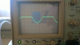
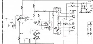
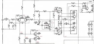
I have a friend's Akai AM-2600 sitting on my bench. There was no sound on the left channel (it had blown before and was repaired by someone else). There was an open resistor in the channel and after replacing it it seemed to work fine again. That is with a load : when an 8R load is connected both channels put out a clean and perfectly equal sine wave. When I disconnect the load the right channel is still fine but the left channel clips the positive side of the sine wave
 . I checked all the voltages on the channel and they're good. Also all the resistors tested good. In the past I had some amps that worked ok without a load but showed problems with one, never this though
  .
.
 . I checked all the voltages on the channel and they're good. Also all the resistors tested good. In the past I had some amps that worked ok without a load but showed problems with one, never this though
 That's a funny one.
Unfortunately I don't have a very good idea what it could be, possibly an iffy connection somewhere around the output stage or SOA protection acting up. I don't think a leaky bootstrap capacitor would do something like this.
Is there really no difference in voltages w/ and w/o a load?
Unfortunately I don't have a very good idea what it could be, possibly an iffy connection somewhere around the output stage or SOA protection acting up. I don't think a leaky bootstrap capacitor would do something like this.
Is there really no difference in voltages w/ and w/o a load?
When I disconnect the load the right channel is still fine but the left channel clips
the positive side of the sine wave
Are you sure the output DC offset is zero in both cases of loading?
C2 and C5 have risen in value (1.2µF and 69µF respectively) but other than that they seem fine. I replaced them just to be sure but that doesn't make any difference. I see that I didn't mention before, without a load, until the power meter indicates about 8w the sine wave is clean, it only start clipping after that.
I did some more research and I found out that the signal starts clipping at 8w with a 60w dim bulb, no load, with a 100w dim bulb it starts clipping at 1W and without any current limiting it doesn't get any signal at all and I have -1.6v on the left channel output. Something seems to have changed because now I have the same results with or without a load.
Without the dim bulb I measure -0.7v instead of +0.7v on the emitters of the diff pair, -3v on the base of TR7, -2v on its emitter, -1v on the emitter of TR6 and -0.3v on its base. The base of TR5 is at -1.9v.
Without the dim bulb I measure -0.7v instead of +0.7v on the emitters of the diff pair, -3v on the base of TR7, -2v on its emitter, -1v on the emitter of TR6 and -0.3v on its base. The base of TR5 is at -1.9v.
I tested all the resistors out of circuit and they're all good, the diff pair has been replaced by a pair of matched KSA992, the caps have been replaced jut in the bad channel, connections tested, and transistors tested (only in diode mode though) and everything checks out fine. The drivers and output transistors have been replaced in a previous attempt and are now TIP31C/TIP32C and 2SB655/2SD675. Here are some of the voltages, without a load, without signal and on full line voltage. It seems that the more I drop the voltages inside the amp the better the channel works (that's probably why at first I said it was working fine with a load but that was with a dim bulb so the higher the volume, the brighter the bulb and the lower the voltages...)


Found it !! I assumed the TIP41/42C drivers were ok as they were installed in a previous attempt just before it was brought to me but that was apparently my mistake. I swapped them for the original drivers on the good channel and the problem moved to the right channel. It's not the first time I had transistors test good with a multimeter but fail in circuit. Is it still possible to get the original drivers for a descent price without having to worry too much about them being fake or should I just go for some equivalents ?
The diff pair has been changed for a pair of KSA992, they have the same pinout as the 2SA640. Now that I got the drivers swapped I get all the right voltages on the left channel and all the wrong ones on the right so I think getting a new pair of drivers will take care of that 
- Status
- This old topic is closed. If you want to reopen this topic, contact a moderator using the "Report Post" button.
- Home
- Amplifiers
- Solid State
- Akai AM-2600 strange issues

