zehner regulator
ok,
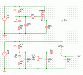
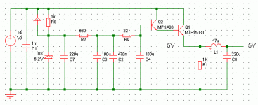
i want to have ~5V. And i don´t want to use 7805. All the circuits with LM317, TL431 etc. use more parts, and so its not really less to use them as to build it discret --> first circuit ?
Whats the purpose of R2, i found it in a circuit on the net.
Now i want 2 times same voltage. As FETs and zehners have not really the same VGS and zehner voltage it would be a lot of matching and i need to order more parts to get 2 identical regulators. Could i do it like in the second ciruit? Disadvantages? and what value for the pot to choose?
Should i use other values for components?
thanks.
Attachments
R to D too?
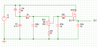
The 100 ohm resistor provides a lower corner frequency for the 220uF filter cap since the impedance of the zener is usually in the range of 10 to 30 ohms. Unfortunately the power supply rejection of the voltage divided formed by 4.7K resistor and the zener has been made about 10 times worse by it's inclusion. Take the resistor out and connect the zener to ground. R2 is now connected between the positive side of the zener and the postive terminal of the 220uF cap. Same filter frequency without decreasing the regulation for the zener. You can make R2 larger and go up to a 1K ohms without any problem. The pot as in the second circuit will work fine. If you put a fixed resistor of 50k ohms between the pot and ground the circuit will be easier to adjust due to the smaller voltage change for a given rotation amount.
The 100 ohm resistor provides a lower corner frequency for the 220uF filter cap since the impedance of the zener is usually in the range of 10 to 30 ohms. Unfortunately the power supply rejection of the voltage divided formed by 4.7K resistor and the zener has been made about 10 times worse by it's inclusion. Take the resistor out and connect the zener to ground. R2 is now connected between the positive side of the zener and the postive terminal of the 220uF cap. Same filter frequency without decreasing the regulation for the zener. You can make R2 larger and go up to a 1K ohms without any problem. The pot as in the second circuit will work fine. If you put a fixed resistor of 50k ohms between the pot and ground the circuit will be easier to adjust due to the smaller voltage change for a given rotation amount.
I built the circuit in #3, and now please don´t lough at me - discovered Vds seems to depend much on current. Between no load and 30mA, the voltage decreases 0,9V.
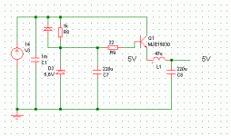
So should i better build instead of the FET a NPN, MJE15030 i have, and low ohm connected a 5,6V zehner, no pot?
The supply should feed a DAC , needs ~ 60mA , additional filter inductor/caps at the DAC.
So should i better build instead of the FET a NPN, MJE15030 i have, and low ohm connected a 5,6V zehner, no pot?
The supply should feed a DAC , needs ~ 60mA , additional filter inductor/caps at the DAC.
Attachments
13mV AC
This 13mV will go straight into your audio. I would not consider it anywhere near acceptable in the DACs I build. You will end up with maybe a 50db S/N ratio if you're lucky. The regulation sucks too and if there is nay load variation, that too will go straight into your sound. The 5V supply for the analog portion of a DAC id very critical.
You should go up to a 6.2V zener and use a darlington connected transistor. Also use a 2 stage RC filter to drive the zener. Either that or a 3-4 transistor feedback type regulator like we made in the 60s. The design of a linear regulator is really quite a complex affair that you are going through to save less than a dollar on a 7805.
The power supply is the foundation of every electronic circuit and if you cut corners there, the rest will never work as well as intended.
I dont know yet if this 13mV is serios, as its only multimeter measure.
For the 2 stage RC filter, what values do you propose?
For the regulator ICs i know they are easy to use, and if i get horrible results i will use them. But first i want try something feedbackless and selfmade. Also i want to put some LC filter stages between PS and DAC.
There are 2 points i see:
- impedance of the PS, if the current of the DAC is continuous it will not bw the bif problem. I don´t know what continuity tha DAC analog supply current is.
- AC coming out of PS. I will fight it with some LC filters and measure with scope again.
update: the scope tells with the circuit above 3mV 50Hz ripple p2p for the +5V and 2,5mV p2p 50Hz ripple for the -5V side.
What would be an acceptable value?
2nd update:
from datasheet:
" As with most linear circuits, changes in the power supplies will
affect the output of the DAC. Analog Devices recommends that
well regulated power supplies with less than 1% ripple be incor-
porated into the design of an audio system."
1% ???
hjelm said:What about a current source instead of R8. Then you could get away with the 100ohm resistor and still have PSRR?
Since this got little attention and seems like a good idea, I'm bringing it back up. What about a CCS? It's basically +1 transistor in addition to what you have there. The exponential PSRR of the diode should provide much less current rippel and therefore a more stable zener voltage.
--
Danny
till said:I built the circuit in #3, and now please don´t lough at me - discovered Vds seems to depend much on current. Between no load and 30mA, the voltage decreases 0,9V.
So should i better build instead of the FET a NPN, MJE15030 i have, and low ohm connected a 5,6V zehner, no pot?
The supply should feed a DAC , needs ~ 60mA , additional filter inductor/caps at the DAC.
You are measuring the wrong thing.
The voltage changes with load because the transconductance of the MOSFET changes with its output current. Remember, transconductance is (delta Vgs) / Id. With a MOSFET, the transconductance varies as the square of the output current.
With no load, there is no Id, and therefore the output impedance is infinite. In actuality there is the load of your meter, but this is not enough to help much. However, when the DAC is connected, the output impedance of an IRF510 will be around around 5 ohms. (This is from a direct measurement of this device on a curve tracer.) This is probably just fine for your application.
If you want to decrease the output impedance of the circuit furher, all you need to do is to add a passive load resistor after the MOSFET. For instance, if you increase the current draw by 40 mA (100 mA total), the output impedance will be around 3 ohms.
I would not use an IC (7805) as this will sound bad. The bipolar will have a lower output impedance (about 0.5 ohms at 60 mA load), but you will probably need to use two parts in a Darlington connection.
EDIT:
While the above is true, you still shouldn't be getting 0.9 V change between no load and 30 mA load. There must be something wrong somewhere. Maybe a bad part or a bad connection. Also, there will be a big positive temperature coefficient with that part and those currents. If the device temperature increases 25 C, you will probably see about 0.25 volt increase in output voltage.
Thanks for that explanations.
With load resistor i get much less voltage difference.
I built the FET version for +-30V of D1 stage now, and it has much less voltage difference, and ripple i can´t measure with my 5mV / 1cm scope.
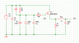
The +5V i build bipolar as picture attached. 50 Hz is also not measurable any more with my scope. But i still have a difference between unloaded and loaded. The AD1865 is speced 22 - 26 mA, i will drive 2 of them for balanced. So i loaded the 5V with a 100R resistor for test. The voltage difference i get between unloaded and 100R load is about 16mV: without load ~ 5.20V witth load about 5.04V. Is this critical, should i change something?
Attachments
The basic problem with this circuit is that it is not a regulator, it is open loop. The performance will vary with the components you chose, but there will *always* be level variations with load, and there will be spikes with digital load. AC ripple performance will also be mediocre, compared with regulators. I understand that you want to use the components at hand, but that will have consequences for the performance.
I'm sorry, but these are life's realities. Circuits like this, basically a DC emitter follower, have their limitations. You may try a heavy standing load like .5A, so that the DAC load variation is relatively small. That will give you better performance for the price of increased dissipation.
Jan Didden
This should be a supply for analog PS of the AD1865, not digital. I don´t know how large are spikes for the analog power supply, but it looks common people ad filters in these supplys that also increase PS impedance. Also spiekes should be buffered with enough cap near to the DAC i thought?
So will i have a problem with the level variation / impedance or with ripple/noise? With more filtering i will have less ripple and noise, and more series resitance that causes level variation with load.
Is thr RC filtering shown in #15 ok, or should i change values?
What about that less 1% riple figure AD tells in the datasheet?
could someone please tell me what would be impedance and ripple figures of his PS in comparison to what i built now?
http://www.geocities.com/yury_g/dac.htm
http://www.geocities.com/yury_g/dac.htm
someone mentioned this earlier but this is essentially an open-loop emitter / source follower. so the output depends on Vgs of the mosfet (output voltage is the zener voltage minus Vgs). Unfortunately, Vgs does change quite a bit with Ids.
One way to get around it is to put a dummy load. Make sure the dummy load is sufficiently large so any variance in the actual load wouldn't be significant (for example, if you anticipate a 10ma output current, put a load that drains about 100ma).
limitations do come with simple circuits. That's life.
- Status
- This old topic is closed. If you want to reopen this topic, contact a moderator using the "Report Post" button.
- Home
- Amplifiers
- Solid State
- zener regulator
