Technology as old as can be.
Not dissing it, all my amps are bootstrapped and it has a unique advantage: it can swing beyond one rail, but certainly anything that can be said about it, was already said loooong ago.
Not that beating dead horses isn´t popular at DIYA (and many other places") )
)
Not dissing it, all my amps are bootstrapped and it has a unique advantage: it can swing beyond one rail, but certainly anything that can be said about it, was already said loooong ago.
Not that beating dead horses isn´t popular at DIYA (and many other places
)The pile of dead horses is very high. There are also so many versions of this topology out there that it's very easy to get lost somewhere between horses and versions.
AKSA is surgical a good thing or bad thing? I prefer the sound of the bootstrap amplifier more then symmetrical designs.
AKSA is surgical a good thing or bad thing? I prefer the sound of the bootstrap amplifier more then symmetrical designs.
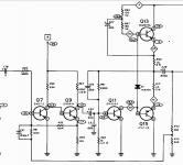
The first amp I built was bootstrapped. Five transistors, and the output PNP was a germanium drift field type. The amp was in a Heathkit AR14 receiver, 20 watts, and wow that was a fun amp, back in 1966. Copied straight from RCA Transistor Manual, I think. I'll post the silly thing.
Bootstrapping has been studied for a long time. Today it is universally used in Class D amps on the high side N channel device, so it's not going away any time soon. Just another circuit topology to be used as needed by designers.
Bootstrapping has been studied for a long time. Today it is universally used in Class D amps on the high side N channel device, so it's not going away any time soon. Just another circuit topology to be used as needed by designers.
Attachments
Member
Joined 2009
Paid Member
I built one that's very close in design to the Baby AKSA and was quite pleased with it. I'd like to do a larger version with 2 pair 21193/94 outputs.
I recently finished just such a beast....
Attachments
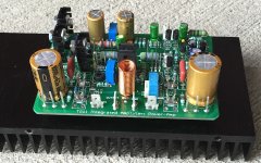
I recently finished just such a beast....
How do you like the sound and performance? Which drivers did you use? Schematic available?
My amplifiers that use bootstrap:
https://anistardi.wordpress.com/2015/09/05/emprit-amplifier/
https://anistardi.wordpress.com/2014/04/19/aksa-55-dalam-simulasi/
https://anistardi.wordpress.com/2014/10/14/perkutut-amplifier/
It is about how to make H2 dominant in THD and wide bandwidth amplifier.
https://anistardi.wordpress.com/2015/09/05/emprit-amplifier/
https://anistardi.wordpress.com/2014/04/19/aksa-55-dalam-simulasi/
https://anistardi.wordpress.com/2014/10/14/perkutut-amplifier/
It is about how to make H2 dominant in THD and wide bandwidth amplifier.
A bootstrapped load works well for the VA stage. They also work great when used to drive the gates of VFET outputs as part of a folded driver stage.
The output stage needs to have enough current gain to drive the upper R without loading it too much, which won't be a problem at all in a power amp. The R and the C form a high pass filter, so you have to select a cap that is large enough so the response does not roll off and LF distortion is low.
Bootstraps are generally found in simple circuits with low-ish feedback and the chief complaint with these amps (usually attributed to the bootstrap current source) seems to be weak bass. If you find this to be the case, before you go replacing the bootstrap with an active load, you might get better results improving the Zout of the amp by ensuring that the PSU impedance is low and high current wiring/pcb tracks kept short and a reasonable guage/thickness.
CRC supplies work well for attenuating ripple but can increase supply impedance if the 2nd C isn't big enough.
A lot of these amp types have large emitter resistors - 0.47 ohm is quite common and I've even seen 1 ohm where there are many parellel output transistors, presumably to reduce current hogging amongst poorly matched parts. I normally use 0.1 ohm for a single pair of BJTs, perhaps 0.22 ohm for parallelled pairs, sometimes omit the Re's completely with single complementary pair of VFETs. Bias stability is very good provided attention is given to the bias generator and sensor location.
My point is that if you are playing around with a circuit using a bootstrapped VA and you are wondering if an active load would improve it, I suggest there are other mods worth trying before going down that road. Enjoy.
Last edited:
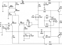
Make R3 trimmable instead.
C14 should go to GND, not -ve rail and should be much bigger perhaps 220p.
You have a lot of very small bypass caps that are not really needed or are too small to be effective.
C6 is probably at least twice as big as it needs to be and will have a big influence on performance. But hard to know without seeing the full circuit.
Edit: C6 is about right as a starting point. You might be able to get it down a little to 82p or 68p with experimentation.
Last edited:
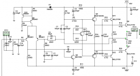
R3 had to be reduced to 430 ohm to 0 the offset. But again, distortion is increased significantly when I remove the offset.
C6 needs to be that large or the circuit does not run smoothly in the emulator.
Output load is 4r.

C6 needs to be that large or the circuit does not run smoothly in the emulator.
Output load is 4r.
Attachments
Last edited:
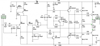
Electrically, R2 *is* at the base of Q7 on your latest schematic. You could solder one end directly to the transistor leg if you wanted to, according to that sch.
The base current drawn by Q6 plus variations in Vbe for different devices types are the reason why R3 isn't exactly double R5 for null offset. In real life you also need well matched input pairs, but simulated devices are usually identical unless you specify otherwise. But I'm supprised 510 ohm gave the best result. Have you built and tested or just simulated? Did you use good transistor models? Is the output stage turned on in your simulation? Increase R13 until there is 15 - 26mV across R18. In a real amp this would be a trimmer for fine adjustment.
C10 is too small to be useful. Its common to use a small plastic cap here (say 100n to 1u) or a small electrolytic (say 1u to 47u).
- Status
- This old topic is closed. If you want to reopen this topic, contact a moderator using the "Report Post" button.
- Home
- Amplifiers
- Solid State
- Bootstrapped amps. DX/Aksa/RCA/etc...