This schematic is based loosely on some aspects of several well respected designs, along with some of my own additions. It's good for over 300W with proper heatsinking. The output devices are MJ or MJL21193/4 pairs, and 2SD669/2SD649 should be used for Q5 and Q6. It has been tested with 55V rails and gives an easy 300W into 4 ohms with 0.01% THD at 20KHz. The bus line in the middle is for later addition of multi-slope current limiting circuitry which I will post shortly.
Enjoy...
Enjoy...
Attachments
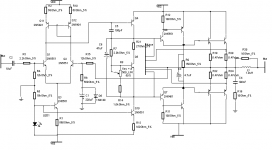
650mW is a bit much for Q4 and Q10, I would have used the 669/649 pair here.The beta of the 669/649 is drooping at 0.5A in the drive stage and 2.4W is a bit much for them too.I would use the MJE15030/15031 .C1 should be a non-polar type with a film bypass and a pair of diodes, C2 needs a film bypass.No supply bypassing is shown.C3 and C6 would benefit fom being sacked film types.Some local feedback in the voltage gain stages would be nice too.
Q7 and Q8 (pre-drivers) are not dissipating 2.4 watts... they are fine as 649/669's. There are two stages of power BJT following them to keep the dissipation low (see below). The power supply is not shown, you are right (along with supply bypassing and assorted fuses, ect). Q4 is ineed what you recommend. The model name somehow didn't make it into the BMP file =).
For example, if the predrivers are conductiong the suggested 0.5A, then the next stage in the CF section would conduct 0.5*20 or 10A, and the EF output stage would be roughly 10*20 or 200A. Highly unlikely -- this is also using worst case Hfe values. I don't personally agree with the use of film caps although it is obviously up to the reader to use whatever he/she pleases.
For example, if the predrivers are conductiong the suggested 0.5A, then the next stage in the CF section would conduct 0.5*20 or 10A, and the EF output stage would be roughly 10*20 or 200A. Highly unlikely -- this is also using worst case Hfe values. I don't personally agree with the use of film caps although it is obviously up to the reader to use whatever he/she pleases.
djk said:650mW is a bit much for Q4 and Q10, I would have used the 669/649 pair here.The beta of the 669/649 is drooping at 0.5A in the drive stage and 2.4W is a bit much for them too.I would use the MJE15030/15031 .C1 should be a non-polar type with a film bypass and a pair of diodes, C2 needs a film bypass.No supply bypassing is shown.C3 and C6 would benefit fom being sacked film types.Some local feedback in the voltage gain stages would be nice too.
Maybe you could update the BMP for us.Q4, the second voltage amp is unmarked and thus assumed to be the complement of it's current source;Q10 identified as a 2N5551.Assuming a red LED the curent would be 1.2V/100R=12mA and 12mA@55V=660mW.The outputs were identified as MJ21193/94 and are rated for a DC beta of 25@8A, less at audio frequencies. 300W/4R=12.25A, or roughly 6A per device, 12.25A/beta of 25=0.489A driver current.Since the pre-drivers Q7 and Q0 are labeled 2N5551/5401 it is assumed the drivers are the mentioned "2SD669/2SD649 should be used for Q5 and Q6"(SIC, 2SB649).A class AB amp with typical bias levels is about 60% efficent (the often quoted 78.5% is for pure class B with a regulated supply.National Semiconductor has a good tutorial under the LM391N and suggests using the 60% figure ), so 300W*.4=120W in the outputs, and 120W/beta of 25=4.8W, and 4.8W/2=2.4W per driver.With a really good heatsink the D669/B649 will do it but the collector current is higher than the beta is specified at.
"I don't personally agree with the use of film caps " I'm hard of hearing and can still hear a HUGE difference between a film and an electrolytic cap in the signal path.
"I don't personally agree with the use of film caps " I'm hard of hearing and can still hear a HUGE difference between a film and an electrolytic cap in the signal path.
I was using 2n's for most of the simulation since it doesn't make much difference other than dissipation which I was ignoring during the design. Hopefully this image clears it up a bit... some of the reference designators were obscured by wires so this color image should help.
All black BJT's are MJ/MJL21193/4
Had to zip it since this forum doesn't allow large images. I made it bigger to show better detail and the rest such as the VI limiting circuit. For the VI circuit, if you compare the two busses, top goes to top, bottom goes to bottom, ect... I didn't want to include the circuit in the middle of the amp schematic. Hope it makes sense.
The multislope limiter reduces maximum output current to a few amps under short circuit conditions to prevent overheating and/or reduced amplifier life. Limiting starts around 2 ohms (purely resistive), although it may become evident with highly reactive 4 ohm loads, but only near full power.
I tried using film and didn't notice a thing - didn't see any difference on the AP either. What kind of difference do you notice?
Attachments
more output devices is nearly all you have to add. Since there are two pre-driver stages it can readily handle the extra base drive for the added output devices (MJL21193/4). The limiting circuitry measures the current through only one pair only, so adding more pairs shouldn't affect its operation, it will only increase the maximum power output with lower impedances.
If you want to raise the supply voltage for more power at 8 ohms there shouldn't be a problem since all chosen BJT's are good for up to 100 volt rails or so..
If you want to raise the supply voltage for more power at 8 ohms there shouldn't be a problem since all chosen BJT's are good for up to 100 volt rails or so..
Thanks; and should the Vbe multiplier be in contact with the heatsink for thermal tracking? How many output devices and what rail voltages would take me to about 500 watts into 8 ohms?
Any measurements yet? Any comments on stability issues while operating at very high power levels? Sorry-too many questions, but thanks.
Any measurements yet? Any comments on stability issues while operating at very high power levels? Sorry-too many questions, but thanks.
The Vcbo of the 2SD669/B649 is 180V, Allowing 10% for line voltage regulation means we cannot use this part with more than +/- 81V. This kind of voltage is what we see in 250W/8R amplifiers. An Adcom GFA585 is a good example of this with 5 pair of outputs per channel. The QSC USA1310 is rated at 400W/8R, but only at 1Khz. It uses 8 pairs of outputs on +/- 95V. The Crown MA2400 will do 525W/8, 20hz~20Khz. It is a bridge amp with only 6 pair of outputs on +/- 57V. I recommend you build a Leach with 3 pair of outputs and bridge. This is a tried and true design with all the parts values specified. Substituting parts in a high voltage, high power design will lead to frequency compensation problems and quite possibly total failure at some point down the road due to instability/oscillation at various load/temperature/drive level combinations. With the correct VA rating in the transformer this will drive over 800W/4R. With 5 pair of outputs per half, 10 pair per bridged channel, up to 1500W/2R is possible. The limit here is how much power the mains socket can deliver.
I agree with djk that 500 watts into 8 ohms is probably too demanding for this amplifier due to rail voltage limitations because of VCE parameters. It can easily be done into 4 ohms however. If you are still interested let me know and I'll forward you some calcs, the FFT, distortion and freq. response curves, ect...
This is frequency response (line is nearly flat) and 2nd and 3rd order distortion with the marker at 1k which calculates the % instead of DB there. The amp is driven to near full power of my prototype (300W) into a 4 ohm load. The abrupt increase in HF distortion is due to the ADC used in the Clio system with has a sampling frequency of only 50kHz. It also cannot measure distortion much lower than 0.05%... this curve was used to demonstrate there were no nasties in the sound.
Attachments
McAnally,
The distortion figures show that 3rd harmonic distortion is slightly more than 2nd harmonic distortion. Hence, is the sound a bit sharp and nasal at higher output levels?
djk, thanks for your input. After a lot of study, I have come to the conclusion that trying for power levels such as 500watts into 8 ohms is rather expensive and risky. My requirement is to drive 8 Nos. 18" EV woofers (horn loaded), either each with its own power amp (400 watts of the woofers + a bit of headroom for the amps) or to be able to drive 1kw bridged into 4 ohm or 1.6kw bridged into 2 ohms. This means four bass bins per side, all paralleled into one bridged amp or 2 each paralleled into 2 bridged amps.
Hence, can this design be operated at lower voltage and more output devices to drive typical low impedance loads as I have stated above.
djk, by the way the 2SD669/B649 devices are used by Randy Slone running at 85volt rails in his OPTIMOS 400 watt designs. Is this sailing too close to the wind? I ask, since this is another design I am considering - 8 mono amplifiers, one for each bass bin.
Thanks again for further inputs,
As for "nasal" sound I don't know... it really sounds quite transparent in my opinion. It isn't uncommon for 3rd order to be a little higher than 2nd order in solid state designs. In the case of driving bass bins, 3rd distortion isn't really applicable. Assume your bins will operate from 40-150hz (for example). 3rd distortion will appear in the 120-450hz range which should naturally roll off by the response of your enclosures. Also, less than 0.1% is pretty hard to hear considering the enclosures are sure to add much more distortion than that.
The amp I presented would be well suited for low impedances given enough output devices are used. I would use a total of 16 (eight top, eight bottom) to drive a 2-ohm load continuously. This keeps the limiting circuitry from even thinking of operating before it should and also gives a good reliability/safety margin.
The amp I presented would be well suited for low impedances given enough output devices are used. I would use a total of 16 (eight top, eight bottom) to drive a 2-ohm load continuously. This keeps the limiting circuitry from even thinking of operating before it should and also gives a good reliability/safety margin.
McAnally,
Thanks. I agree with what you say about 3rd Harmonic Distortion. I will try out your design with more output devices as suggested by you. I suppose 8+8 output devices should give about 600 to 800 watts continuous into 2 ohm loads with a dual supply of 55-60 volts. This suits me fine as I can bridge the amp into 4 ohms.
One last question. Instead of MJL devices suggested by you, would it be possible to use 2SC3281/2SA1302 devices, adding up more devices to handle low impedance loads. Ofcourse, it would require 14 or 15 devices per bank to handle 2 ohm loads. But availability and cost are factors that prompt me to ask this question.
Overall this is a great contribution by you to the DIY community. Keep it up!
I'm not quite sure. I have only a single pair of those and they work fine, however I haven't tried with multiples yet. I would suggest using a higher value for the compensation cap to start since I think the 2sc/2sa's are a little faster and you dont wanna get unstable with that much power =). Another tip, build a test circuit on a breadboard with the power devices on a heatsink seperate from the board and if that works you should be set since this is a worst case setup. I haven't tested the circuit at the power levels you are suggesting... but it should work in theory. I would be very interested to know about your results.
Samuel Jayaraj said:McAnally,
Thanks. I agree with what you say about 3rd Harmonic Distortion. I will try out your design with more output devices as suggested by you. I suppose 8+8 output devices should give about 600 to 800 watts continuous into 2 ohm loads with a dual supply of 55-60 volts. This suits me fine as I can bridge the amp into 4 ohms.
One last question. Instead of MJL devices suggested by you, would it be possible to use 2SC3281/2SA1302 devices, adding up more devices to handle low impedance loads. Ofcourse, it would require 14 or 15 devices per bank to handle 2 ohm loads. But availability and cost are factors that prompt me to ask this question.
Overall this is a great contribution by you to the DIY community. Keep it up!
McAnally,
That was a quick reply. You are right regarding the compensation cap. I will buy a bunch of the 2SC/2SA devices and get started off. These require a smaller base bias than the MJL devices, so the driver stage shown in your schematic should handle this well. Since each transistor would be contributing a lower power than as shown in your schematic, the protection circuit may need some adjustment of values. Keep me posted if you have any calculated values. I will post the results here. Thanks again.
That was a quick reply. You are right regarding the compensation cap. I will buy a bunch of the 2SC/2SA devices and get started off. These require a smaller base bias than the MJL devices, so the driver stage shown in your schematic should handle this well. Since each transistor would be contributing a lower power than as shown in your schematic, the protection circuit may need some adjustment of values. Keep me posted if you have any calculated values. I will post the results here. Thanks again.
djk said:Some local feedback in the voltage gain stages would be nice too.
If the amp is to be used for higher power output than originally spec'd (300w) I recommend 100-200 pF of capacitance from collector to base of Q6 and Q7 and a small (22 ohm) degeneration at the emitter of Q4. This will ensure stability with certain loads and nasty circuit layouts. I've now got eight pairs of MJL21193/4's at the output with excellent performance and no signs of instability with almost no turn on thump and none at turnoff. I have yet to boost the rails up to +- 80V but as soon as the new caps and toroid come in I'll post the results.
As per the recommendation of Nelson Pass I've included a seperate LED for the voltage reference on Q10 just in case. Thanks for all the input guys.
- Status
- This old topic is closed. If you want to reopen this topic, contact a moderator using the "Report Post" button.
- Home
- Amplifiers
- Solid State
- Here's a high-power amp 4 u guys