Hi,
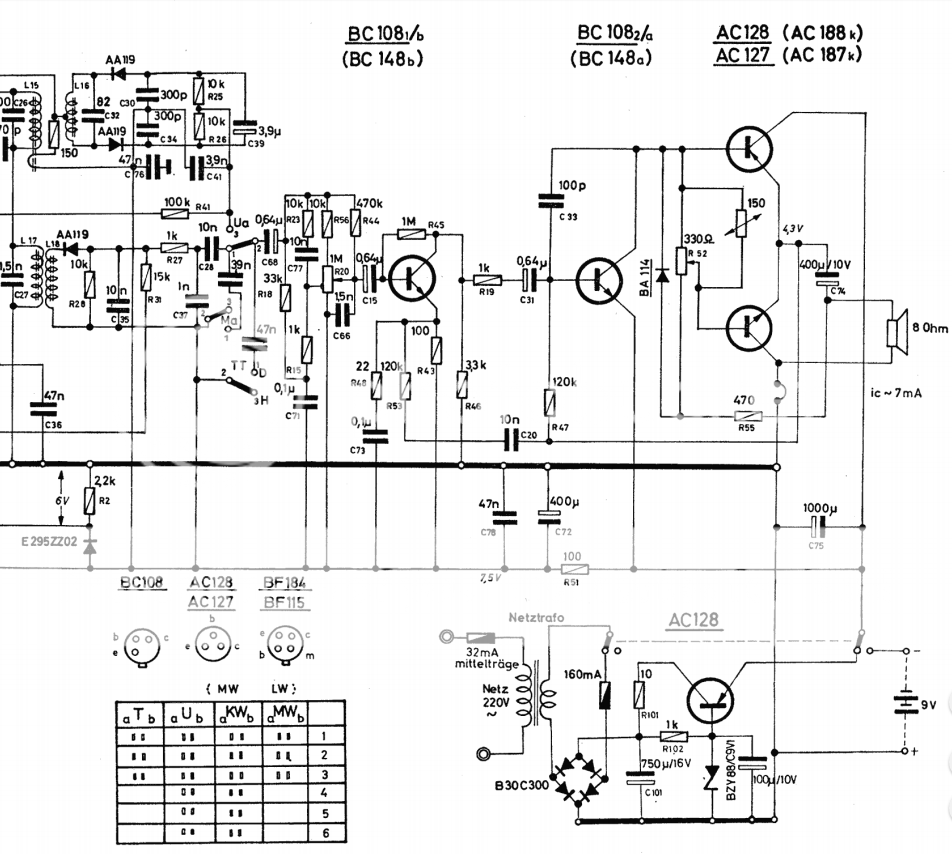
I've been playing around vintage germanium radios and converting them into cool little guitar amplifiers. So far it's been (mostly successful), but I was focused only on earlier amplifier topology with all PNP germanium transistors, phase splitter transformer and output transformer. It was pretty easy to split the circuit between radio and amplifier section, usually just after the volume pot and connect that to the input jack. I wanted to check out more recent circuits from the late 60s that have silicon transistors in preamp and AC187/AC188 and no transformers. Now I'm having difficulties getting it to run. I have replaced all electrolytic capacitors with fresh ones, removed the volume pot and connected input signal to the input cap. When I connect the power supply and speaker I do hear some faint hum, so it seems to be working at least partially, but as soon as I connect the guitar it goes mute. Below is the schematic, before and after I butchered it...and few questions:
* Grounding got me all confused. I understand that this is a NPN circuit...but why is ground connected to + side of the battery? Everything looks backwards to me")
* what are all those resistors and capacitors around the volume pot doing? This has the be the most complicated volume control I've seen. Usually there's signal coming from the radio part of the circuit, volume pot acts as a voltage divider and that's it. This pot has 4 lugs and is marked 50+420K, seems to be tapped. I disconnected everything, so now the signal goes to the input cap directly. No other resistors or caps are in the circuit before the first transistor.
* Germanium gain stages I'm used to have a voltage divider on the input that applies voltage to the base. I don't see that done here. Is that ok?
* Should input signal be applied between input capacitor and ground (thick) line or the 7.5V line (thin line)? I tried both and neither worked, although I believe that the former is correct.
* Do I need a reference resistor between base and emitter?
* what is AC128 doing in the power supply?
Sorry for the long post
Thanks,
Bane
I've been playing around vintage germanium radios and converting them into cool little guitar amplifiers. So far it's been (mostly successful), but I was focused only on earlier amplifier topology with all PNP germanium transistors, phase splitter transformer and output transformer. It was pretty easy to split the circuit between radio and amplifier section, usually just after the volume pot and connect that to the input jack. I wanted to check out more recent circuits from the late 60s that have silicon transistors in preamp and AC187/AC188 and no transformers. Now I'm having difficulties getting it to run. I have replaced all electrolytic capacitors with fresh ones, removed the volume pot and connected input signal to the input cap. When I connect the power supply and speaker I do hear some faint hum, so it seems to be working at least partially, but as soon as I connect the guitar it goes mute. Below is the schematic, before and after I butchered it...and few questions:
* Grounding got me all confused. I understand that this is a NPN circuit...but why is ground connected to + side of the battery? Everything looks backwards to me
* what are all those resistors and capacitors around the volume pot doing? This has the be the most complicated volume control I've seen. Usually there's signal coming from the radio part of the circuit, volume pot acts as a voltage divider and that's it. This pot has 4 lugs and is marked 50+420K, seems to be tapped. I disconnected everything, so now the signal goes to the input cap directly. No other resistors or caps are in the circuit before the first transistor.
* Germanium gain stages I'm used to have a voltage divider on the input that applies voltage to the base. I don't see that done here. Is that ok?
* Should input signal be applied between input capacitor and ground (thick) line or the 7.5V line (thin line)? I tried both and neither worked, although I believe that the former is correct.
* Do I need a reference resistor between base and emitter?
* what is AC128 doing in the power supply?
Sorry for the long post
Thanks,
Bane
Its not all NPN. Look at the top transistor in the output stage (PNP). This is a complementary push pull PNP/NPN configuration.
Grounding is arbitrary and this one happens to use 'positive earth'. Probably a throwback to earlier designs and also it uses a PNP germanium series regulator in the power supply. Another reason sticking with pos earth.
All the R's and C's around the volume pot will be to create a non flat audio response (like a loudness control) that varies according to the volume setting.
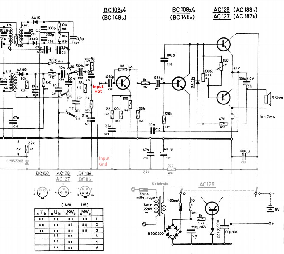
One possible problem... you seem to be reverse biasing C15 because that is the negative rail you are trying to use as 'ground'. Use the thick black line as ground. That is where all signals are referenced to.
Grounding is arbitrary and this one happens to use 'positive earth'. Probably a throwback to earlier designs and also it uses a PNP germanium series regulator in the power supply. Another reason sticking with pos earth.
All the R's and C's around the volume pot will be to create a non flat audio response (like a loudness control) that varies according to the volume setting.
One possible problem... you seem to be reverse biasing C15 because that is the negative rail you are trying to use as 'ground'. Use the thick black line as ground. That is where all signals are referenced to.
thanks for the prompt reply. I replaced C15 and C31 with non-polarized poly film capacitors, so the signal should flow either way. When I hit strings really hard, some faint signal does come through the speaker...like a buzz or pop.
One of the reasons I used negative rail as input ground is because volume control is grounded there. Will try to switch to the positive ground.
One of the reasons I used negative rail as input ground is because volume control is grounded there. Will try to switch to the positive ground.
Last edited:
Its a bit of an odd circuit tbh. You will see that the reservoir cap, the rail decoupling, the speaker and the series regulator are all referenced to the thick black line which is 'ground.
The transistor the volume control connects to should really be PNP to keep with the positive ground philosophy with the emitter referenced to the positive ground... however
If the amp isn't working as expected then do the basic check of measuring the midpoint voltage of the output stage (the emitter of the two output transistors) and make sure it is approx half the supply voltage.
Thanks. I measured the midpoint voltage and it's slightly less than the 1/2 V+. Measured around 3.7-3.8V. Should I play with the bias trimmer to adjust it? Is that what it's intended for?
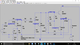
I think that the output stage is functional, suspect it has to do with the butchering I did around the input stage. I'll try to inject the signal after the first transistor and see if I get anything on the output.
Shouldn't there be some sort of reference resistor on the base of the first transistor? The second transistor is referenced to the midpoint through the 120K (R47) resistor, but the first transistor base "floats". Not sure how that works.
What kind of voltages should I expect on the two "preamp" transistors?
Thanks again, appreciate your help.
Bane
The preset looks as though it adjusts the bias current rather than midpoint voltage. So be careful if you alter it. That 'link' in the collector of the output stage transistor is to insert an ammeter to set the required current, which is probably very low, perhaps only a couple of milliamps.
I see, there is a label at the schematic that says 7mA and some sort of a node drawn, maybe that's what it is. On the PCB I saw a weird jumper below the board used instead of a trace, so it's probably where one would measure the current and install the jumper when happy.
Is there anything else I could tweak to adjust the midpoint voltage or it's down to the output transistors' characteristics?
Is there anything else I could tweak to adjust the midpoint voltage or it's down to the output transistors' characteristics?
The 1M resistor provides bias, DC feedback, and AC feedback. The downside of this bias method is that the collector voltage depends on the transistor current gain, so the next stage has to be AC coupled - but it probably would have been AC coupled anyway so no great loss in flexibility. It also means that the current gain can't be too high or too low as this would force the transistor too near cutoff or saturation and so limit collector voltage swing.
The 1M resistor provides bias, DC feedback, and AC feedback. The downside of this bias method is that the collector voltage depends on the transistor current gain, so the next stage has to be AC coupled - but it probably would have been AC coupled anyway so no great loss in flexibility. It also means that the current gain can't be too high or too low as this would force the transistor too near cutoff or saturation and so limit collector voltage swing.
thanks, that's interesting. And in the second stage, bias is also achieved through the feedback loop? I see a 120K resistor going to the midpoint between the output transistors.
I debugged some more, here's additional info, maybe it would help:
* tried grounding the input to the other ground. That's the case I described before, there's no sound, but if I apply strong enough signal I get a pop at the output
* while I was measuring voltage between ground and input transistor collector I got sound at the output. It was quiet and distorted though, but definitely audible. Looks like DMM shorted something and got it to work
* Also tried to connect input signal to the collector of the input transistor and got the sound that's not distorted but fairly quiet
* measured voltages: first transistor's emitter is at V+, collector and base are the same and around 0.5V lower. second transistor C = 3.8V (midpoint voltage), B = 8V, E = V+. Does that sound right?
Thanks again!
Found the issue! Yesterday I cut the PCB in half, discarding the section that has the receiver circuit. One of the ground traces that connects the 3.3K resistor to ground was running around the board and I cut it. I made a jumper to connect the resistor back to ground and got it to work!
There's a minor issue now, it squeals unless I touch the speaker, but it's probably a grounding issue, the worst part is over.
Thanks all for the input!
Btw, you are right, all voltages are negative.
There's a minor issue now, it squeals unless I touch the speaker, but it's probably a grounding issue, the worst part is over.
Thanks all for the input!
Btw, you are right, all voltages are negative.

- Status
- This old topic is closed. If you want to reopen this topic, contact a moderator using the "Report Post" button.
- Home
- Amplifiers
- Solid State
- Need help understanding AC187/AC188 radio amp circuit