I did some changes on the amplifier pcb, based on the experience of the first version. There will be 4 series connected resistor in the feedback chain, to reduce the dissipation on each of them.
I put small connector to the pcb to use for bias monitoring, which makes the settings more comfortable.
Change the values of the DC balance setting circuit, the old version was able to set up to +/-3V which was hard to adjust down the mV range.
Sajti
I put small connector to the pcb to use for bias monitoring, which makes the settings more comfortable.
Change the values of the DC balance setting circuit, the old version was able to set up to +/-3V which was hard to adjust down the mV range.
Sajti
Last edited:
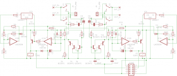
Housekeeping schematic attached.
There are the 3 common function:
- 2second turn on delay
- DC protection
- overtemperature shut down
Sajti
Pcb?
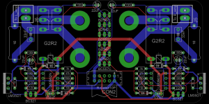
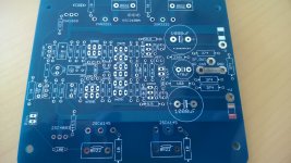
Here is the picture of the pcb.
There are some minor changes, as I had many BC327, so I use them instead of BC516. Works very well, only 0,1V loss on it... All values are on the pcb to easy implementation. Output relay is Omron G2RL2 12V coil version.
The pcb is Pcbway friendly designed. You can get 10pcs. for 5USD+delivery. Gerber is available if You need.
This pcb has connection to the housekeeping psu pcb, which contains small EI tansformer, and inrush current limiter, driven by the turn on delay circuit.
Sajti
Attachments
I use this binding post:
Dual Female Banana Plug Terminal Binding Post for Speaker Amplifier LW
The pcb was desingned for it.
Sajti
Dual Female Banana Plug Terminal Binding Post for Speaker Amplifier LW
The pcb was desingned for it.
Sajti
Nice Board
You do a really nice looking board.
I would like to propose you to use larger tracks than you use to do. It will improve the overall board quality and reliability in the project in general.
Thank you for schematics and PCB from housekepping circuit
Regards
Ronaldo
You do a really nice looking board.
I would like to propose you to use larger tracks than you use to do. It will improve the overall board quality and reliability in the project in general.
Thank you for schematics and PCB from housekepping circuit
Regards
Ronaldo
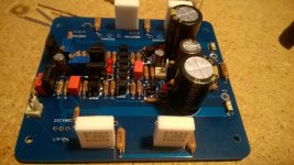
I would like to propose you to use larger tracks than you use to do.
The critical wires are 5mm wide, and they are enough, even with 4 ohm load. There was no significant voltage drop, or heating.
Sajti
The critical wires are 5mm wide, and they are enough, even with 4 ohm load. There was no significant voltage drop, or heating.
Sajti
Yes, I saw it.
Please, understand it was a suggestion to improve your nice work.
I know is easier to use thin tracks as it can run in small areas, but no doubt with larger traces you will have best final work.
The board become more reliable (with even less voltage drop in signal tracks) and you can make more changes in the board during development without board damage.
It is a point of view, of course you are own of your work
Regards
Ronaldo
Nice!
Where is connect the speaker gnd ,on amplifier board or on power supply board?
From the amplifier pcb. There is star gnd point on each amplifier pcb.
Sajti
Do you believe that is the best option?From the amplifier pcb. There is star gnd point on each amplifier pcb.
Sajti
Did you test FFT this way?
Do you believe that is the best option?
Did you test FFT this way?
Yes I believe, that it's the better solution with dual mono psu.
Sajti
Do you believe that is the best option?
Did you test FFT this way?
Your way make me feel a little bit embarrassment when you said connecting Speaker GND back to power supply better than connect to power amp board. However, many commercial expensive amp that are also use same as it.
- Status
- This old topic is closed. If you want to reopen this topic, contact a moderator using the "Report Post" button.
- Home
- Amplifiers
- Solid State
- V6 amplifier