Pioneer M-22 Refurbishment
I'm reading through this post and finding some valuable information.
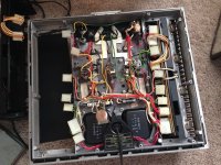
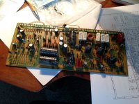
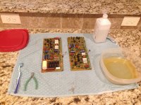
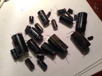
I'm wondering if anyone ever found a suitable replacement for the relays within the unit or if just cleaning them has worked fine? I recently purchased an M-22 and am in the process of refurbishing it. The only known problem with my unit was the left channel being intermittent but working great otherwise. So far I have cleaned the unit and boards, burnished the relay contacts. Also, I went ahead and replaced all the electrolytic caps on the boards. I'm waiting on three caps to arrive before reassembling and adjusting.
Once I start to re-assemble the amp should I leave the covers off the PCBs, attach the left and right channel modules then put the amp on its side to Adjust the DC balance and Idle as there is no easy way to reach the VR1 and VR2 pots? Also, manual shows +80mV for DC balance, should this be as close to 0 as possible and Idle set as manual shows 850mV? Thanks in advance for help.
I'm reading through this post and finding some valuable information.
I'm wondering if anyone ever found a suitable replacement for the relays within the unit or if just cleaning them has worked fine? I recently purchased an M-22 and am in the process of refurbishing it. The only known problem with my unit was the left channel being intermittent but working great otherwise. So far I have cleaned the unit and boards, burnished the relay contacts. Also, I went ahead and replaced all the electrolytic caps on the boards. I'm waiting on three caps to arrive before reassembling and adjusting.
Once I start to re-assemble the amp should I leave the covers off the PCBs, attach the left and right channel modules then put the amp on its side to Adjust the DC balance and Idle as there is no easy way to reach the VR1 and VR2 pots? Also, manual shows +80mV for DC balance, should this be as close to 0 as possible and Idle set as manual shows 850mV? Thanks in advance for help.
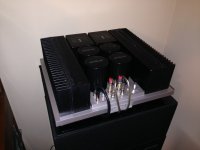
Attachments
It could easily be an error, but I will say that I have some amplifiers which
exhibit a "reliable" drift with temperature, so I set them with a little offset
when cold and they drift toward zero as they warm up.
The test is whether the amp is close to zero after warmup.

an other approach is the introduce of an offset servo.
What says Pioneer itself about missprints in their service-Manuals?
Are there Service-Bulletin with updates (was usual from Philips at those days)?
First ask there for an appropriate address of service center for Pioneer vintage Audio components:
1) Pioneer/Elite CA Privacy Rights, 18 Park Way, Upper Saddle River, New Jersey 07458, USA.
2) Pioneer & Onkyo Europe GmbH Gutenbergstraße 3, D-82178 Puchheim, Germany; By e-mail: http://www.eu.onkyo.com/en/contact-42204.html.
Why would you want to put the amp on its side? The pots can be accessed from above with a regular screw driver (that fits), if at least these are still the original pots or an appropriate replacement. Btw, I would strongly advise to replace these pots, if you haven't done so already.
DC balance according to general concensus should be 0 (zero) mV when warmed up. And idle, yes, 850mV seems to be quite high, but I do not think this is a typo in the manual.
I have been looking for a replacement relay and if I recall well it should indeed be there, although in the rebuild I did I just polished the contacts of the existing relay. To my opinion, if the contacts are not burned in and polishing is done carefully (not to remove a very thin top cover) the existing relay will be as good as a new one.
Well after replacing all the caps, I had an intermittent channel so I opened up the case and tapped around and it would come on. I figured the relay was the culprit so I went to test the voltage and zap! Next thing I know there is smoke on the right side! Turned off and unplugged. I traced it down to one of the output transistors (tested all four). I have some replacements on order. In the mean time I discovered an unsoldered cap lead so I'm betting that was my intermittent channel issue. I just hope the output transistor is all that was zapped!
Thanks for the notes Jeromach! I've now replaced the ceramic caps and diodes in the high temp area and raised them off the board a bit to give them room to breath. Also, I've used your list to order the replacement transistors in case I need them as well as the trim pots (i'll change these right away as mine looks dusty and dirty). Once I get the replacement 2SA744 in I can check the unit out further and check the balance and idle. Is there a point on the board that I can check to see if the proper voltage will be going to the 2SA744 prior to connecting the wiring? Perhaps checking the voltage on Pins 13, 14 or 15 but I would need to know the anticipated value.
Hey guys, ok some good luck I tested voltages on the left board for the main transistors and had the same values approx. on the right side so I installed the 2SA744 that came today and turned the system back on and all seemed stable. I adjusted after 10 mins. the idle to approx. 850 and everything held nicely. I set the outputs to approx. 15-20mV and they stayed stable there. Put the casing back on and hooked it back up to my main system and i'm back where I started! Intermittent to no audio from left channel, only crackling at high volume. I've checked the output cables and the input cables by switching them to the opposite channel and everything works there. So what am I missing? Maybe a bad transistor on the left PCB?
Did you actually buy a SA-744? If so, where did you get it from?
I believe Omron does have suitable replacement relays, but I do not have a part number. I remember having seen one when I was browsing through Mouser parts lists, but I think I forgot to make a note of it. But of course you can try it too.
I believe Omron does have suitable replacement relays, but I do not have a part number. I remember having seen one when I was browsing through Mouser parts lists, but I think I forgot to make a note of it. But of course you can try it too.
Yes I purchased 2 Qty. and the probe tests on the replacement were very similar to the originals. Seller ended up sending me 6 more as his description originally stated 4 qty. for the purchase price. Thinking it was a mistake I ordered 2 to be sure but he honored the description and sent me 6 more. I'll see what i can find on the relay. So far I haven't had any luck but the one that's installed seems to be working fine now. I also added some larger rubber feet to the bottom of mine to give more room for cables to go underneath and to feed more air through. System is sounding excellent now.
For those working on M22 caps and relays, you may find this link useful:
The Pioneer M22 as a head amp? (and recapping guide) | Super Best Audio Friends
The Pioneer M22 as a head amp? (and recapping guide) | Super Best Audio Friends
- Status
- This old topic is closed. If you want to reopen this topic, contact a moderator using the "Report Post" button.
- Home
- Amplifiers
- Solid State
- Pioneer M-22 class A amp mistake in service manual?