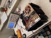
I'm now going to present to you my latest construction, it's also my favorite one.

As you can see it has a floating power supply so that the amp can be made very simple. Notice the current source Is1 - it sets the bias that goes through Q1/Q7. The special arrangement with the cascodes and the auxiliary PS sees to that the power losses will be dramatically reduced from about 240W to about 40W. The current through the cascodes may be set to approximately 150mA by the means of some regulating circuitry.
I have built a prototype, I will not give you a complete schematics and I will not describe the circuit very well unless some of you think the circuit is quite interesting, then I will describe it more in detail. Someone I spoke with thought it was a great circuit and he advised me not to publish it here on diyaudio.com - I should certainly start manufacturing it instead he thought. But I don't have the right connections and marketing skills so for me it's more fun to find out what you guys think of it.
First of all, it's not a "blameless" amp. It's a philosophical one - it's constructed under the presumption that simple circuits, preferably driven in class A and more preferably driven in single ended class A actually has the most appealing sound to our ears. Why so? Well, make a google search on the subject - some of you agree some don't. But if you really are in the this thing, this amp really excels, and furthermore, without needing a lot of cooling fins.
OK, the THD is around 0.2% (2:st order harmonics), and the higher orders are rapidly declining, well below 0.02% ( 3:rd order ). If you think 0.2 percent 2:nd order is quite much, then regard the fact that tests have indicated that 2:nd order harms must be well over 5% to be audible. ( Ask tubefreaks ).
The damping factor is around 40 to 50.
And please excuse the crappy schematic - it was the one I made simulations on and I had to add som resistors and others just to avoid the spice emulator to crash.
First I auditioned it on my old Snell E3 speakers and it immediately stood clear that it was something special. Later on I hooked it up on my B&W804D speakers. I really thoughtthose speakers was a bit too big bite for my little amp, but not so at all. Now it's virtues really came out. Actually this is the first amp where I can tell the difference between a mp3@320 file and an uncompressed file.
Attachments
Vzaichenko. The solution for the Igen is an IRF540 in conjuction with a bc546 and a small feedback loop.
But the schematics is really sketchy and only intended to give you a hint of the principle working. If you perhaps want to build one yourself, I will certainly send you the complete schematics. That one includes a feed forward circuit to stabilize the various currents.
And then, my prototype is e baby version. A "real" one should have at least 6A bias and +-50V PS. Then the power losses for two channels will be appr. 180W and that's not much for a single ended amp. My final schematics also includes an important update.
And, Gagdx. Please give me an example of an amp with bottles on top") . A canadian phrase, I presume.
. A canadian phrase, I presume.
But the schematics is really sketchy and only intended to give you a hint of the principle working. If you perhaps want to build one yourself, I will certainly send you the complete schematics. That one includes a feed forward circuit to stabilize the various currents.
And then, my prototype is e baby version. A "real" one should have at least 6A bias and +-50V PS. Then the power losses for two channels will be appr. 180W and that's not much for a single ended amp. My final schematics also includes an important update.
And, Gagdx. Please give me an example of an amp with bottles on top
. A canadian phrase, I presume."bottles": long thin glass cylinders or tubes (there's a hint). I think gabdx likes his "bottles" to have wires coming out of the bottom (sometimes the top) and when they work they glow in the dark......very attractive and many people think they sound better than highly refined sand in black plastic blobs with wires coming out the bottom.....
Cheers, Jonathan
Cheers, Jonathan
- Status
- This old topic is closed. If you want to reopen this topic, contact a moderator using the "Report Post" button.