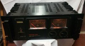
Interesting dilemma here. I`m putting a newly acquired amp through its paces and for some reason, the left channel negative cycle starts to clip prematurely at only 21VRMS (147w) into a 3 ohm load were its right channel counterpart puts out a healthy 42 volts (588w) into the same load. The positive wave wont clip till about 40 volts are reached.
8 ohm and 6 ohm come in at 49volts (300w) and 47.7 volts (380w) respectively on both channels, +/- .5volt.
These are 1khz sine waves measured at the points of clipping, single channel driven.
The amp seems completely stock, unrepaired, modified or otherwise butchered.
What would cause such a condition?
Cool amp BTW")
8 ohm and 6 ohm come in at 49volts (300w) and 47.7 volts (380w) respectively on both channels, +/- .5volt.
These are 1khz sine waves measured at the points of clipping, single channel driven.
The amp seems completely stock, unrepaired, modified or otherwise butchered.
What would cause such a condition?
Cool amp BTW
Attachments
Hi Michael,
Charles is probably right. There are sensing resistors that come from each emitter resistor, and if something bad happened to the amp it might have cooked one or more emitter resistor. The amplifier would continue to operate like it should until the voltage developed across the emitter resistors is high enough to trip over-current protection.
These can be made to sound pretty darned good. The schematic shows that they are home amplifier type designs, but made really rugged. I've done a bunch recently, and people are more than happy with their amps. BTW, those volume controls are integrated switched resistor networks that can be cleaned. It's no picnic getting them out, but well worth the effort if they are noisy.
By "doing" the amplifiers, I mean total strip down, clean and rebuild the heat sink assys, and going through the PCBs carefully. That effort creates a whole new amplifier that performs much better.
That amp is a keeper.
-Chris
Thanks for chiming in Charles, Chris. I kind of figured the issue wasn't too grave in nature as the amp otherwise works perfectly into lighter loads.
Looking at the output section, are you referring to the 10 ohm resistors just before the emitter resistor? PNP or NPN side? Can they be tested in-circuit? What type and what are their power ratings?
Sorry for the newb questions
Looking at the output section, are you referring to the 10 ohm resistors just before the emitter resistor? PNP or NPN side? Can they be tested in-circuit? What type and what are their power ratings?
Sorry for the newb questions
Attachments
Hi Michael,
They are 10R, 1/4W carbon film resistors as I recall. Because they are in parallel almost, you will have to lift one end of each to measure them. Do the same to the emitter resistors and measure each one. You will have to short your meter leads and subtract that reading from the measurements you get on all these resistors because the resistances are low. A meter with a Kelvin measurement (4 wire) function would be the proper instrument to use here. That's even with one lead on each resistor lifted.
-Chris
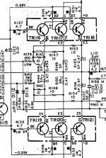
You need not lift them, they are essentially in parallel, so measure one where it sits. If you see 3 ohms, then all three are intact, if you see 5 ohms, one is open, if you see 10 ohms two are open. I will leave it to you to determine what the reading would be if all three are open.
In my experience, those 0.47 ohm resistors are wirewound, and usually are not off value. Mostly they are either OK or open.
You cropped the picture, but off to the left, those three 10 ohms feed the base of a small transistor. If enough current flows through the 0.47 ohms, then the 10 ohmers turn on that small transistor, which in turn clamps your driver bases (or predriver, whatever). I donl;t recall here, but often the collector of the small transistor will connect to the driver base via a diode. if you simply lift one end of that diode from each limiter collector, that disables the limit function. And then you can find out if the limiter was what was clipping your output.
OK I looked it up, TR113,114 are the limiters of which I speak.
Of course the limiters might be working, so you can monitor the voltage across each 0.47 ohm resistor - indicative of current - and see if one is working harder than the rest.
Hi Enzo,
Guess what? I recently had a P2200 where both types of resistors had some examples where the resistance was higher than they should be - by a substantial amount. Yes, I was using an HP 34401A in four wire mode for the measurements. I had to lift one lead of each resistor to prevent making a stupid assumption.
Also, resistors with a mark indicating over heating need to be replaced as well no matter how they read when you measure them.
Now Enzo, do you know what kind of meter Michael has? I don't either, but there is almost a 100% chance it is 2 wire resistance only with cheap leads. You're going to have him measure parallel resistances and use that to deduce a possible resistor open or value change? How about more than one resistor off value (they are in parallel you know).
How about this for an idea. Let's get people to make fail safe resistances that do not require a crystal ball to guess at conditions in this circuit? I don't know about you, but on my bench, I make certain my conclusions are based in fact. Remember, multiple devices can be affected in circuits such as these. I have repaired a lot of these amps over the years, and can tell you for certain that you cannot assume resistors are either open or fine.
-Chris
Hi Michael,
Please ignore short cuts. You'll have to slide the tubing off the resistors and examine them for discolouration also. If you are in doubt, for the money, replace it. If you have some emitter resistors open, replace the lot on that one channel.
Resistors do not have a polarity, so no NPN or PNP types. Check them all on that channel. How would you feel if you continued to have trouble and a service person found a defective resistor that you should have checked? Slow and steady, no guesses or wishful thinking. Only reality counts.
Best, Chris
PNP or NPN resistors?
uh oh, all these years i thought resistors didn't have polarity...
could there be an output not conducting? it been a while since i've had one on the bench but aren't the output transistors on sockets?(i recall encountering bad sockets and the quick fix was soldering them)
Last edited:
Hi Turk 182,
Nope. Those are very good sockets that are screwed onto the heat sink individually.
Soldering a transistor into it's socket? So you're the guy! It makes later service a cramp in the ... you know. There are other ways to solve that issue that don't nail the poor guy who gets to work on it next.
It's true. The person who is hurt by bad service the most is the next good technician. The customer may be charged a bit more, but you can't charge for all the time it takes to fix situations like that.
My other sore point are those people who don't clean up and use new grease. Cracked insulators, old grease and debris. Those jobs often fail again.
-Chris
Hi Turk 182,
Yeah, you're probably right.
My pet peeve is bad advice contradictory to good advice recently posted (by anyone, not just me).
I was jesting with you, but probably was lost in translation. "So you're the guy!" was meant as a joke, as if you were the only person doing that. A peek of my normal good humor. Sorry if that stuck at you.
-Chris
Hi Michael,
You've got the PCB out, and that was easy, still tethered to the power supply unless you undo all that too. Since you have it out, check both sides in case the amp was run very hard as it would cook both positive and negative sides. Start anywhere you please, but be thorough. It's much more difficult to back in later - yes?
What would I do - scratch that. What do I do? I check both sides as you can't overheat just the positive or negative side unless you have a large DC offset. You would have noticed that.
I was trained partially by an excellent technician who was Austrian. Zero shortcuts, and for very good reason. He was a tough instructor, but he made me into a very good technician. I'm just passing the knowledge along.
-Chris
OK. I`ll measure the 10 ohm resistors and attempt the emitter resistors too. By attempt I mean it may prove difficult to measure a .47 ohm resistor when I short my leads and read 1 ohm . Meter is a Fluke 75 with Fluke probes and wires.
I`ll report back with my findings. Thank you gents!
. Meter is a Fluke 75 with Fluke probes and wires.I`ll report back with my findings. Thank you gents!
Ok, then avoid making stupid assumptions.Hi Enzo,
Guess what? I recently had a P2200 where both types of resistors had some examples where the resistance was higher than they should be - by a substantial amount. Yes, I was using an HP 34401A in four wire mode for the measurements. I had to lift one lead of each resistor to prevent making a stupid assumption.
Me neither, and in principle I assume it´s the typical yellow $10 one *everybody* has, UNLESS specifically stated otherwise.Now Enzo, do you know what kind of meter Michael has? I don't either, but there is almost a 100% chance it is 2 wire resistance only with cheap leads.
In fact I bet even you at least have one of them
Ok, let´s get real.You're going to have him measure parallel resistances and use that to deduce a possible resistor open or value change?
The cheap $10 meters, being 2 terminal, typically show a residual resistance value, with probe ends shorted, between 0.3 and 0.6 ohms, absolute worst case with a very dirty one, kept in a humid place (so banana plugs are grimey), might show 0.9 ohms .
In any case, probes must be shorted first, indicated error noted and then substracted from resitance measurement.
Result will be within 0.1 and 0.2 ohms of actual value, not Lab quality but WAY more precise than needed in this case.
these are carbon film or metal film resistors, not 1940´s carbon composition ones, so in general they are stable, I have never seen modern resistors way off value unless they were in flames, have seen many quite browned ones and still measuring within rated tolerance.How about more than one resistor off value
Remember, here we must decide between 10/5/3.3 ohms, not between 10.01 and 9.98 ohms and for that decision, a $10 meter is enough.
At least in the Real World of servicing
If you are used to work in a high precision Lab, congratulations, but don´t expect an average user, not even an average Tech to hold same standards because it simply is not realistic.
I BET he knows(they are in parallel you know).
In fact his analysis and suggestion is based on that, just reread his post
Having a bad day?How about this for an idea. Let's get people to make fail safe resistances that do not require a crystal ball to guess at conditions in this circuit?
Having a bad day?[2]I don't know about you, but on my bench, I make certain my conclusions are based in fact.
Do you KNOW who Enzo is?Remember, multiple devices can be affected in circuits such as these. I have repaired a lot of these amps over the years, and can tell you for certain that you cannot assume resistors are either open or fine.
Who are you addressing as a noob would be Tech?
He is THE tech to ask about problems in the Musical Instrument Electronics World.
Official Service Tech for ALL the most important brands out there ... including Yamaha of course
, of which he has repaired *hundreds* (if not *thousands*) Now go tell Nelson Pass or Bob Cordell that they should hone their Technical skills, so the day is not wasted
Or pray this bad day ends quickly.
UPDATE
Measured all 6 10 ohm resistors, they checked well. The emitter resistors not so.
All but one came in at around .8 ohms. Factoring in inherent meter and probe resistance of .2ohms, that figure seemed right, however, R144 was open.
Can that possibly be the issue? All were tested out of circuit btw. Should I replace only that one or all 3 on the PNP side?
Well, there´s your problem:
R144 open means that one transistor is not pulling the load, which also means that increased current through the remaining ones (R150/156) drops a higher than expected voltage which triggers protection earlier.
Everything adds up.
In theory, a new 0.47 ohms one would be enough, but since they are inexpensive, (and remaining ones have been overheated), replace all 3 .
- Status
- This old topic is closed. If you want to reopen this topic, contact a moderator using the "Report Post" button.
- Home
- Amplifiers
- Solid State
- Yamaha P2200 asymmetrical clipping