This is a handy thread and has a lot of things I'm looking for.
Good advise,
Disagreement,
Standing up for your self,
Standing up for others,
And more importantly looking out for the guy who's
going to be doing work on it and not assume the persons
skills, knowledge, and experience match yours.
Play fair and no cheating.
Now, shake hands and go to your corner's
when the bell rings come out fighting.
......Ding!
Now that we got that out of the way,
if you find one of these amps floating around
or have one that you aren't using, please send me
a PM as I am in need.
Cheers,
Sunc
Last edited:
Hi Jim,
As for the expected resistance values, or discrete values you assume, your assumption is based on a single complete failure. It doesn't hold where there could be multiple failures and resistances that have changed. I have just recently repaired three of these amplifiers and ran into exactly that. I did try using total resistances and got an intermediate value. Then I did it the right way (as described in my post) and got the real answer. I had an open resistor and one that was over one ohm - in a wire-wound. You are making assumptions.
Now I may not be a famous technician, but I did warranty service for Yamaha and others in the MI field, and also the recording studio industry. I am locally well known, and really don't want to be a guru or superstar. That takes too much time and you don't always live up to the reputation. Everyone has bad days, even you do.
I've trained many technicians who have gone on to be very successful in industry. They wisely decided that the music industry doesn't pay as well as it should for skilled people. And I didn't treat Enzo as a "noob would be Tech". I know he knows what he is doing, even if I don't know his stature in the industry. He gave bad advice in this situation and I called him on it.
Was I grumpy at the time? Yes, and probably came on too strong. But I hold people skilled to a higher level than someone fresh out of college or university. So for that, Enzo, I apologize for a stronger than should have been response. All I will say is that you have to consider who you are giving advice to. You aren't right there to explain and watch as if he was a tech at a bench in front of you.
Anyway, sorry to offend you Jim. But step back and have another look at this. You came on far too strong as well.
-Chris
Emphasis was yours, not mine. Please quote exactly.I had to lift one lead of each resistor to prevent making a stupid assumption.
Cheap leads can have highly variable resistance. Even old, good leads can. You should know this better than anyone with your experience. I'm relating what I have actually seen and experienced. There is a reason that labs use only good leads that aren't too old.The cheap $10 meters, being 2 terminal, typically show a residual resistance value, with probe ends shorted, between 0.3 and 0.6 ohms, absolute worst case with a very dirty one, kept in a humid place (so banana plugs are grimey), might show 0.9 ohms .
Yes, in normal operation they typically do not drift in value that much - unless they were over loaded at some point. They can even go open without showing a burn. All you can see is a small black dot between the resistor and PCB. They can go down in resistance, then drift up until they go open. I've seen this many times. Even when the part is only very slightly discoloured. I have over 40 years of service under my belt now and still going.these are carbon film or metal film resistors, not 1940´s carbon composition ones, so in general they are stable
Sure, whatever you say. A skilled technician with experience can take short cuts intelligently. However, someone starting out should do things the proper way to avoid avoidable mistakes. You would know enough to short the leads, then move the wires around to see if the reading changes. You should anyway. Someone who hasn't been bit with variable resistance wouldn't know to do that.Remember, here we must decide between 10/5/3.3 ohms, not between 10.01 and 9.98 ohms and for that decision, a $10 meter is enough.
As for the expected resistance values, or discrete values you assume, your assumption is based on a single complete failure. It doesn't hold where there could be multiple failures and resistances that have changed. I have just recently repaired three of these amplifiers and ran into exactly that. I did try using total resistances and got an intermediate value. Then I did it the right way (as described in my post) and got the real answer. I had an open resistor and one that was over one ohm - in a wire-wound. You are making assumptions.
No, I didn't. However, his advice might work for us, but not to a person who isn't a trained technician. You, Enzo and I all know enough to take short cuts, but we are observing other things about the repair that can suggest when a shortcut is a wise move or not.Do you KNOW who Enzo is?
Which makes the advice he gave even worse. He knows better, and he knows he isn't dealing with a technician here. As do you. That is what pissed me off about his post.He is THE tech to ask about problems in the Musical Instrument Electronics World.
Official Service Tech for ALL the most important brands out there ... including Yamaha of course , of which he has repaired *hundreds* (if not *thousands*)
Now I may not be a famous technician, but I did warranty service for Yamaha and others in the MI field, and also the recording studio industry. I am locally well known, and really don't want to be a guru or superstar. That takes too much time and you don't always live up to the reputation. Everyone has bad days, even you do.
I've trained many technicians who have gone on to be very successful in industry. They wisely decided that the music industry doesn't pay as well as it should for skilled people. And I didn't treat Enzo as a "noob would be Tech". I know he knows what he is doing, even if I don't know his stature in the industry. He gave bad advice in this situation and I called him on it.
Was I grumpy at the time? Yes, and probably came on too strong. But I hold people skilled to a higher level than someone fresh out of college or university. So for that, Enzo, I apologize for a stronger than should have been response. All I will say is that you have to consider who you are giving advice to. You aren't right there to explain and watch as if he was a tech at a bench in front of you.
Now that was a pretty ignorant response. I'll let that go as you are obviously up late and might be a little punchy. My day ended at midnight and I had already admitted I was grouchy before your post. I'll bet you read that one post and went straight to a response.Now go tell Nelson Pass or Bob Cordell that they should hone their Technical skills, so the day is not wasted
Anyway, sorry to offend you Jim. But step back and have another look at this. You came on far too strong as well.
-Chris
If the associated transistor were faulty, would that not be apparent in full power 8 and 6 ohm tests?
All emitter and 10 ohm resistors displayed no signs of heat discoloration or other damage including the open one FWIW.
I have a .5 ohm 5Watt resistor on hand, can that be used as a substitute in place of the .47, even temporarily for the sake of confirming that was indeed the problem. I would need to order a .47 online as I cant source these things locally.
I`m considering doing a recap at some point but for the time being,I would just like to get the amp up and running.
Hi Michael,
The 0.5 R resistor is the same thing as a 0.47 R resistor, so install it and you can call the repair done if everything else checks out.
Hi Andrew,
If that transistor was shorted, best case scenario would be that the base resistor opened up before horrible things began to happen. Of course, they never do open that fast and horrible things would have happened. At the very least you would see the other sense resistors cooked a bit and more damage in the output stage.
-Chris
I don;t take this stuff personally.
When I train technicians I often preach this: "never think up reasons not to check something". So I have no objection per se to pulling parts to test them thoroughly. And I agree, it takes a certain level of experience to know when short cuts are appropriate and when not. But in my defense here, I was looking at this repair as at the triage level, not yet to the involved repair stage. Instead of a lot of assembly and disassembly, we can do a number of faster checks to get an idea how extensive is the damage.
This is the emergency room, and we are assessing the patient. The MRI, lab work, and other advanced care comes later.
yes, of course that 10 ohm resistor could be off value, heck we could have one open and the other two raised in value to make it look like two were open. Or some such. But most times, those little guys burn open or don;t. Same with the cement ballast resistors. So a quick check usually tells me this is an area for more concentration or perhaps I can get more information by looking at other areas.
Case in point those two limiter transistors. I can tear apart that whole circuit with the 10 ohms and stuff, or I can lift two diodes and ignore them for now. If I find that the symptom did not change, that is hopefully news that the limiters are not causing the issues. If the symptom DID change, then I know I need to concentrate on that area aside from anything else I find. That is classic divide and conquer.
I think most techs, or at least many, see a new repair on the counter, they do not immediately take the boards out and start removing parts. I think they more often make some strategic tests and observations to find what we are up against.
There are as many strategies for good troubleshooting as there are good techs.
Hi Enzo, Jim,
Completely agree. I train techs to get as much information from the unit as possible before tearing it down - unless the faults are obvious. We make good use of variacs to enable tests at reduced power levels, and variable DC supplies for switching power supplies.
Once they are into the parts pulling stages, yes. Check everything that makes sense and keep your nose and eyes open for other clues.
Sorry for Mr. Grumpy coming to the party guys.
-Chris
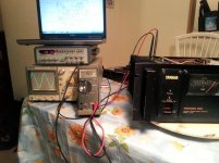
Some final numbers here:
302 wpc @ 8
384 wpc @ 6
591 wpc @ 3
Single channels driven to threshold of clipping, 1Khz.
.005 and .004 volts of DC offset
Bias adjusted and stable at 10 mv.
Those are pretty impressive figures, especially for a 40 year old amp ! I like how it tolerates very low impedance's, unlike my BGW 750B and Peavey CS 800. My PC2002M too is unfazed by low impedance's, puts out in excess of a 1Kw with both channels running..
The P2200 will be pressed into duty shortly driving some Kappa 7s, should be interesting")
I will likely do a recap in the future (and replace all 3 emitter resistors ) as I know how beneficial that can be for not a lot of money.
Many thanks to ALL that contributed to this thread. Although I do have some electronics knowledge, it has been a lifelong ambition to be able to repair items such as this and when successful, the sense of accomplishment is most satisfying. That would not be possible without the aid of good folks such as yourselves, a tip of my hat to you all.
302 wpc @ 8
384 wpc @ 6
591 wpc @ 3
Single channels driven to threshold of clipping, 1Khz.
.005 and .004 volts of DC offset
Bias adjusted and stable at 10 mv.
Those are pretty impressive figures, especially for a 40 year old amp ! I like how it tolerates very low impedance's, unlike my BGW 750B and Peavey CS 800. My PC2002M too is unfazed by low impedance's, puts out in excess of a 1Kw with both channels running..
The P2200 will be pressed into duty shortly driving some Kappa 7s, should be interesting
I will likely do a recap in the future (and replace all 3 emitter resistors ) as I know how beneficial that can be for not a lot of money.
Many thanks to ALL that contributed to this thread. Although I do have some electronics knowledge, it has been a lifelong ambition to be able to repair items such as this and when successful, the sense of accomplishment is most satisfying. That would not be possible without the aid of good folks such as yourselves, a tip of my hat to you all.
Hi Michael,
You should see just how nice this amp can be.
Right now the PC2002 should sound a lot nicer (just did one) than the P2200. Through some component changes and very close matching of the input pair, it will sound closer to the PC2002. That's the best hint I can give you except to say that this can be one of the better sounding amplifiers even compared to the home amplifier lot.
-Chris
I agree totally, my bone stock PC2002M is the finest sounding amplifier I`ve owned and I`ve owned amps from the likes of Bryston, Classe, Krell and others. It would probably still hold it`s own with the best that is out there even today.
Now that you piqued my interest even further, what can be done to these stock units that will bring them to another performance level?
I did a recap of a BGW 750B as suggested by fellow poster DJK which yielded significant results, a similar upgrade would be easily justified in this case.
Now that you piqued my interest even further, what can be done to these stock units that will bring them to another performance level?
I did a recap of a BGW 750B as suggested by fellow poster DJK which yielded significant results, a similar upgrade would be easily justified in this case.
Hi Michael,
Most of the improvement stuff I do is by hand, so not easily explained how to do it. Matching the input pair is obviously labour intensive and I use a jig designed for that specific purpose. Other replacements are sometimes a judgement call depending on how things look from a past use point if view (like how hot did this look like it got). What I can tell you is that I rebuilt one of these for a gentleman who drove a long way to get here. He later bought more of these amplifiers and delivered them to me for the same work. He will be getting rid of the other amplifiers he was using. These do get close to the PC2002 for sound quality. Not bad for a vastly simpler design.
About replacing capacitors. There is no one "best capacitor" type. They each excel for different purposes, and choosing a replacement must take that into account. There are also value ranges where some capacitors are not made, so you have to come up with the next best thing in those instances. The most critical thing is maybe not something we think about. The replacement capacitor must fit properly where the old one did. There are also some resistor changes that are done with that model. Again, no one type of resistor is "the best". Each has an application where they stand out as the best choice.
When I rebuild one of these amplifiers, I strip it down and clean each heat sink. I let them soak for a day each and scrub them. That lowers the thermal resistance and keeps debris away from the output mounting surfaces. This is something you can do. Use either dish washing soap, or something like "Simple Green" (Canadian Tire stores). Immerse the heat sinks completely. I imagine you could use a dishwasher for this, but your wife might kill you!
I'm not trying to be mysterious, there are things that are difficult to explain and the concepts would require that I send you a BOM and directions, which I do not have time for. Do your best and I think it will sound better.
-Chris
- Status
- This old topic is closed. If you want to reopen this topic, contact a moderator using the "Report Post" button.
- Home
- Amplifiers
- Solid State
- Yamaha P2200 asymmetrical clipping