All the disadvantages of quasi-comp, with split supply none of the cheap speaker protection. One bad solder joint, DC happens on the speakers with direct coupled transistors burning voice coil or ripping suspension. This design is also missing the 10 ohm base resistors on the 2n3055 required for modern 2 mhz Ft parts to not oscillate, which the original 200 khz parts didn't need. You can't buy original homotaxial 2n3055 anymore, RFE only.
Look up Apex AX6, similar parts count but single supply and stupid proof on the speaker. AX6 is also PNP in the input transistor. 2n3773, 2n3055, no difference except toughness. I'm building point to point AX6 with the TO3 transistors off the driver board.
Bigun TGM8 has an npn input transistor but is still speaker capacitor protected. John Ellis Basic 50 has more parts but better PSRR (power supply rejection ratio) and stil a stupid proof speaker cap.
I overheated my speaker cap coupled ST120 amp and set fire to the driver boards, without hurting my $150 each PA speakers a bit. If you do select split supply amp like amp camp or honeybadger, buy the protection board too or use $3 throwaway speakers from the junkyard/resale shop.
Last edited:
Thank you for your advice.
Ok, main problem is speaker protection. I use uPC1237 for protection.
I use this amp for quite a long time without problems, and it's have pretty clear sound.
Now I want more power, about 100-150W on 8Ohm, and searching for simple but good amplifier schematic.
Ok, main problem is speaker protection. I use uPC1237 for protection.
I use this amp for quite a long time without problems, and it's have pretty clear sound.
Now I want more power, about 100-150W on 8Ohm, and searching for simple but good amplifier schematic.
for 150W into 8ohms you will need ~±56Vdc to ±60Vdc for the supplies.
This is usually given by a 40-0-40Vac transformer.
For two channels you need somewhere from 300VA to 600VA.
Each output stage needs ~700W to 800W of total device dissipation capability. i.e. 2pairs of 200W devices or 3pairs of 130W devices in each amplifier.
Now go and search for amps that meets those requirements..
Glad your old circuit worked for you, it looked competent if low power. You possibly had original slow Ft 2n3055 so you didn't need the OT base resistors .
For 150-200 W/ch, honeybadger comes as a board or kit from diyaudio store, see the sticky thread up top of the forum. Diyaudio store is a button on the top options line. Honeybadger does require a center tap transformer, so buy the speaker protection circuit add on kit. The PWB is a little long for my existing enclosures, but two would fit in a metal fold top file cabinet, for example, a $5 solution to the packaging problem. I need metal packaging, I'm close to a street where CB radio enthusiasts drive by emitting annoying RF signals .
UPC1237 is a good fault sensor, to trigger a relay disconnect of speakers on DC detect. When I tried to buy some there weren't any in stock. For a 1300 W amp with ****y crowbar to ground protection I find the 8 v silicon bilateral switch (diac) bs08d from powerex to be a modern in stock sense solution. The sbs is fed from the speaker line by a resistor/capacitor to ground time delay filter, and the signal out the back triggers a latching circuit to turn on the disconnect relay drive. I'm using a bidirectional input (two LED's back to back) optoisolator to trigger the set of my 74HC74 latch. Power up reset triggers the reset line of the latch, and toggle is grounded. An HC part will put out about a milliamp to energize something, I use PN2222 transistors to drive red/green indicators, and in series some FET driver IC's.
Last edited:
I make this amplifier, and not to start working properly. Always something burn. terrible amplifier.
Audio Amplifier 90-100W with 2N3773
Audio Amplifier 90-100W with 2N3773
Your assessment is the same as mine.
A terrible amplifier.
Look here for a much better 2N3055design employing the famous Quad Triples o.s.. This design, according to a number of builders including YT, is a very fine performer for just a handful of €/$. It did compete favorably with my Crimson CE608's.
Good Luck,
Eelco
€
http://www.diyaudio.com/forums/solid-state/242341-audio-amplifier-2n3005-3.html
Good Luck,
Eelco
€
http://www.diyaudio.com/forums/solid-state/242341-audio-amplifier-2n3005-3.html
Oh, not *that* bad, although it´s certainly a dated design (at least 40 y.o.).
It *should* work, problem is (will also happen with any other design) that in SS amplifiers, being fully DC coupled, any wiring or assembly error will often straight burn nthe expensive power transistors and carry a lot of other parts to the grave ... very frustrating.
I suggest you build a lamp bulb limiter, a 40/60W **incandescent** (not CFL/fluorescent/Led) light bulb in series with mains voltage which minimizes excess current in case of problems and lets you measure and correct instead of going up in a puff of smoke.
With way over 10000 amplifiers built, I *still* plug any fresh built one in the current limiter for the first time on, go figure.
Only after it tests normal it can be plugged straight into mains.
Yes agree ,this is the best testing method if a variac isn't available.Oh, not *that* bad, although it´s certainly a dated design (at least 40 y.o.).
It *should* work, problem is (will also happen with any other design) that in SS amplifiers, being fully DC coupled, any wiring or assembly error will often straight burn nthe expensive power transistors and carry a lot of other parts to the grave ... very frustrating.
I suggest you build a lamp bulb limiter, a 40/60W **incandescent** (not CFL/fluorescent/Led) light bulb in series with mains voltage which minimizes excess current in case of problems and lets you measure and correct instead of going up in a puff of smoke.
With way over 10000 amplifiers built, I *still* plug any fresh built one in the current limiter for the first time on, go figure.
Only after it tests normal it can be plugged straight into mains.
I consider the Mains Bulb Tester a less damaging first turn on method compared to a Variac. I have both.Yes agree ,this is the best testing method if a variac isn't available.
Hi
I really do not understand why this amplifier 2N3773 works problems.
1. I use Bulb Tester 60W, and everything was fine.
2. I set quiescent current about 75 mA, 50 mV over R14 and R15 resistor
3. Output voltage cca 3mV
4. I put on the base of the output transistor 10 Ohm resistor, to prevent oscillations.
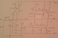
I find this same schematic with voltage level, schematic is attached.

On this schematic driver transistor have a driving voltage 1,2V and -1,2V , but in my amplifier I have
1,25V and -0,62V.
I do not understand why I can not have the same voltage as shown in the schematic.
I decided for this amplifier because of output power and because it is not complicated and is similar to my old amplifier. (schematic is on first post in this thread).
I gave up on this amplifier, burned me 10 transistors and a few resistors.
I really do not understand why this amplifier 2N3773 works problems.
1. I use Bulb Tester 60W, and everything was fine.
2. I set quiescent current about 75 mA, 50 mV over R14 and R15 resistor
3. Output voltage cca 3mV
4. I put on the base of the output transistor 10 Ohm resistor, to prevent oscillations.
I find this same schematic with voltage level, schematic is attached.
On this schematic driver transistor have a driving voltage 1,2V and -1,2V , but in my amplifier I have
1,25V and -0,62V.
I do not understand why I can not have the same voltage as shown in the schematic.
I decided for this amplifier because of output power and because it is not complicated and is similar to my old amplifier. (schematic is on first post in this thread).
I gave up on this amplifier, burned me 10 transistors and a few resistors.
Last edited:
If you don't have a wiring error (difficult with a PCB but not inpossible) then check for oscillation at the base of Q8, the place where the DC voltage is -0.6 instead of -1.2. DVM miss a lot of what goes on.
Short the input, put on light bulb limiter box, check that point with a scope. No scope, (I don't have one working) check with 2VAc scale of an analog voltmeter. Connect negative of analog voltmeter to analog ground through a 0.47 uf capacitor. (analog voltmeter will read DC voltage on AC scales).
If significant voltage, and you can't hear anything in the speaker, try again with a 390 pf capacitor blocking the negative probe. If still have significant AC voltage, you have ultrasonic oscillation.
A similar amp, engineered out more carefully is the Panasonic Sa-73. Perhaps you can take your current parts collectioni and make a few modifications to achieve that schematic. Thread is http://www.diyaudio.com/forums/soli...across-emitter-quasi-complimentary-stage.html
If you don't have a wiring error (difficult with a PCB but not inpossible) then check for oscillation at the base of Q8, the place where the DC voltage is -0.6 instead of -1.2. DVM miss a lot of what goes on.
Short the input, put on light bulb limiter box, check that point with a scope. No scope, (I don't have one working) check with 2VAc scale of an analog voltmeter. Connect negative of analog voltmeter to analog ground through a 0.47 uf capacitor. (analog voltmeter will read DC voltage on AC scales).
If significant voltage, and you can't hear anything in the speaker, try again with a 390 pf capacitor blocking the negative probe. If still have significant AC voltage, you have ultrasonic oscillation.
A similar amp, engineered out more carefully is the Panasonic Sa-73. Perhaps you can take your current parts collectioni and make a few modifications to achieve that schematic. Thread is http://www.diyaudio.com/forums/soli...across-emitter-quasi-complimentary-stage.html
Thanks for the good advice.
I forgot to mention that I worked simulation in LTspice, and I get same voltage level.
Here are the voltages provided by the simulation

Hi x2x
Your second schematic is an improvement > adds bootstrap bias but still missing a few details and parts values.
Going from memory I believe the PNP quasi pair needs a diode and parallel 100 ohm ( this will fix your different measurement concern -0.62 to -1.2 = a Vbe + missing diode )
so sorry The internet is a place of dubious schematics > Just copy the Dx or the original RCA data book (circa 1970) circuit. E.g. single pair of 2N3055 and +/- 42Vdc ~ 70W / 8 ohm
I wouldn't buy '2N3055' today you don't know what youll get really, there's much better genuine ON Semi for not much more.
Last edited:
Hi x2x
Your second schematic is an improvement > adds bootstrap bias but still missing a few details and parts values.
Going from memory I believe the PNP quasi pair needs a diode and parallel 100 ohm ( this will fix your different measurement concern -0.62 to -1.2 = a Vbe + missing diode )
so sorry The internet is a place of dubious schematics > Just copy the Dx or the original RCA data book (circa 1970) circuit. E.g. single pair of 2N3055 and +/- 42Vdc ~ 70W / 8 ohm
I wouldn't buy '2N3055' today you don't know what youll get really, there's much better genuine ON Semi for not much more.
Thank you infinia
1. I made simulation in LTspice with Baxandall diode and parallel resistor.... and you were right, I get correct voltage symmetry on driver transistor.
")
Today I learned something new. I knew that Baxandall diode affects the linearity of the amplifier, but I did not know that affects the voltage symmetry.
2. Today I realized that I was burnt headphone output on my smartphone. I used a smartphone as a audio input source for the amplifier.
Bad idea.
Probably the inconsistent impedance at the output of smartphones and the amplifier.
Basically, this is another reason why my amplifier was work strange.
Testing prototype amps, I drive the input with a $5 transistor AM/FM radio I fished out of the trash . I paralleled the boogered volume control with a fixed resistor. It puts out about 1.5 vac on station through the earphone jack. The 1/8" stereo phone plug to double RCA jack adapter costs more than the radio, but is worth the $6 it cost. If I blow up the radio with a circuit error, $6 lost, not $200 for a smart phone.
If you tune to a rock station on the radio, you can see the beats of the music as you test through the amp with an analog VOM. That way if you find a high steady AC voltage, you know it is RF oscillation or LF hum - no beats show on the VOM needle.
Panasonic SA-73 per link in thread 15 was very close to your schematic, with important differences. I hope you can modify your current board with jumpers and land cuts to try that instead. Those phase control capacitors between C and B, and B and E, I just solder those to the traces themselves. 10 pf weighs almost nothing.
Honey Badger PCB is huge, it uses TO-246 or 263 or TO3P transistors instead of TO3, and is a split supply speaker burner. One bad solder joint (I make some) in the wrong place on a split supply amp, there is DC voltage on the speaker.
There were versions of the SA-73 with single supply and a speaker series cap, which protects your speaker for $3 instead of a 12 part another prototype protection board. A series speaker cap saved my $75 each speaker in a performance when my "repaired" first solid state amp went up in a ball of flame. Quasi-comp amps can return the speaker to the negative rail, instead of the center tap of the transformer, which keeps the speaker cap positively charged at all times. Passing through zero volts with a negative to negative electrolytic speaker cap sounds stupid, I tried it already on a CS800s. Film 3300 uf 63 VAC caps can't be bought, and would be huge if you could.
Best of luck.
Last edited:
- Status
- This old topic is closed. If you want to reopen this topic, contact a moderator using the "Report Post" button.
- Home
- Amplifiers
- Solid State
- 2N3055 amplifier - is this good amp ?