I'm still not very good at figuring this stuff, can someone help me out? How is the 2 amp figure calculated
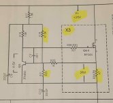
Its from the Pass aleph 30 service manual. This portion of the circuit sets the bias on the output devices at 2 amps. Not shown, the drain of the output mosfets connect to R34-R36
(Please ignore the highlights, they're there for another reason)
Its from the Pass aleph 30 service manual. This portion of the circuit sets the bias on the output devices at 2 amps. Not shown, the drain of the output mosfets connect to R34-R36
(Please ignore the highlights, they're there for another reason)
Q6-Q8 are set at 2 amps DC by the network consisting of Q5 and the components surrounding it. Q5 is biased by R17 and R18 and series. Capacitor C9 is used to reduce supply noise. R20 serves to sense the current running through Q6, and feeds that to the base of Q5 forming a loop that holds the output current at 2 amps. The PN junction drop of Q5 forms the reference voltage for the system.
R19 is a fixed resistor with trims the DC current value. R21 and C10 adjust the current against the output current as sensed by the voltage across R34.
Attachments
Vbe of Q5 should be ~0.6V
You have added 0.25V to the sch. Why?
That's straight from the manual, i didn't change anything. On the analogous aleph 60 schematic, its 0.37V
Vbe of Q5 should be ~0.6V
You have added 0.25V to the sch. Why?
There's R20 between that voltage and the base.
You have incorrectly assumed that the current through R20 is zero. You have incorrectly assumed that the VBE of Q5 is 0.25 volts. Neither of these assumptions is correct.Q5 can't control with only 0.25V
It won't work as a CCS if Q5 is switched off.
You forgot to include resistors R19, R17, and R21 in your analysis. Try it again.
If output DC current is 2A and R34-36 are .47ohm, voltage should be more than 300mV instead of 250mV.
Vbe(Q5) is V(R20) + V(R34-36).
V(R20) depends on R17-19 & Q5 network, if you increase R19 you decrease the current in R20 (and V(r20)) then you increase output current to keep
V(R20) + V(R34-36) = Vbe(Q5)
If you decrease R19, you decrease output current.
Vbe(Q5) is V(R20) + V(R34-36).
V(R20) depends on R17-19 & Q5 network, if you increase R19 you decrease the current in R20 (and V(r20)) then you increase output current to keep
V(R20) + V(R34-36) = Vbe(Q5)
If you decrease R19, you decrease output current.
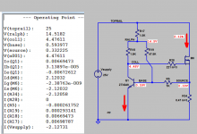
Here is what LTSPICE says. I used the multiplicity option "m=" to simulate the X3 nature of the output pullup structure Q6-8, R28-R30, R34-R36.
Don't expect simulation accuracy down to the millivolt, especially when you didn't fit the device models yourself, ESPECIALLY if you have to substitute different part numbers because you don't have model param values for the actual parts in the actual circuit!
_
Don't expect simulation accuracy down to the millivolt, especially when you didn't fit the device models yourself, ESPECIALLY if you have to substitute different part numbers because you don't have model param values for the actual parts in the actual circuit!
_
Attachments
- Status
- This old topic is closed. If you want to reopen this topic, contact a moderator using the "Report Post" button.
- Home
- Amplifiers
- Solid State
- Current source calculation question