Hi minek123,
Decided to power with 12 DC, can I lose the 4148 diode
Added 100nf snubberand 12v owner to protect MOSFET,but I don't understand idea of catch diode which is connected to amps rails and to speaker output ,if you know can u explain me ,if I do it do I have to implement in both channels.
Some members ex(thimos/stillforgiven)in 100 watt ultimate amplifier thread used apex design reported slight hum and no reason or solution given by anybody,
Is any hum or distortion contributed by this to output ,what is your experience
I am avoiding relay in thinking that is faster,safer and better,can u advice
1) no hum introduced by this circuit. it's dead silent.
2) 4148 diode can go away if not fed from AC. 5.5k resistor may need to be increased a little in this case, to make sure voltage on pin 4 is around 4.7V. you can check in the datasheet what is max voltage on pin 4. most likely 5.5k will be ok.
the reason to feed it from AC, is to detect power-off condition immediately (before psu capacitors discharge) and turn off speakers right away.
without it, sound in speakers will slowly fade away, instead of being turn off right away.
3) catch diodes: https://en.wikipedia.org/wiki/Flyback_diode
to protect FETs from voltage spikes coming back from inductive load (speaker)
hi minek123,
i am planning to feed from transformer via separate rectifier in to dc dc bucky(for better regulation) ,not via psu
i am mentioning about the circled one, why to connect amps rails, seen may mosfet dc protec in forum , none seem to have it
i am planning to feed from transformer via separate rectifier in to dc dc bucky(for better regulation) ,not via psu
i am mentioning about the circled one, why to connect amps rails, seen may mosfet dc protec in forum , none seem to have it
Attachments
hi minek123,
i am planning to feed from transformer via separate rectifier in to dc dc bucky(for better regulation) ,not via psu
i am mentioning about the circled one, why to connect amps rails, seen may mosfet dc protec in forum , none seem to have it
Many amps (especially BJT) have catch diodes employed.
E.g.
https://www.flickr.com/photos/danielminek/28980670581/in/album-72157672599707885/
https://www.flickr.com/photos/danielminek/29001688581/in/album-72157671653862832/
Many FETs have diodes built in, so external diodes are not rally needed.
Do MOSFETs have a diode built into them? - Electrical Engineering Stack Exchange
IRFP240 datasheet, Pinout ,application circuits Power MOSFET
> why to connect amps rails?
If voltage spike comes from inductive load, it has to go somewhere.
Last edited:
hi minek 1243,
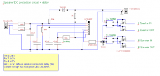
redrew cad to 12v , as per your circuit, just added snubbers and zener between gate and source, left the catch diodes as i will chose a mosfet with body diode , if its absolutely necessary i will add, please advice
my amp max dc rail voltage is 56v,max power 250 watts in 4 ohm
considering value
1.is 100v mosfet is enough or do i have to go for 150v
2. minimum amps recommended for above
3. minimum rds on resistance
will choose low cost one with minimum criteria
Attachments
hi minek 1243,
redrew cad to 12v , as per your circuit, just added snubbers and zener between gate and source, left the catch diodes as i will chose a mosfet with body diode , if its absolutely necessary i will add, please advice
my amp max dc rail voltage is 56v,max power 250 watts in 4 ohm
considering value
1.is 100v mosfet is enough or do i have to go for 150v
2. minimum amps recommended for above
3. minimum rds on resistance
will choose low cost one with minimum criteria
Depends on your amp. how much power (voltage) it gives.
I would go for 150V or 200V
Vds must be higher then sum of rail voltages.
In general, you are seeking for a MOSFET with very high Vdsmax, very low Rdson and very high Idmax.
The mosfets mentioned on the circuit (IPI11ON20N3), are good enough for most amps, with low Rds.
Another good fit:
IPD200N15N3G 150V 0.020ohm 50A
IRFP90N20D 200V 0.023ohm 94A
IPB025N-10NG,
IRFB1227 200V 0.0197ohm 130A
IRFB3607,
IRFS59N10D 100V 0.025ohm 59A
IRFB4227PBF 200V 0.024ohm 65A
I don't think Zeners are needed - they are to protect Gates of FETs.
When driven by optocoupler, DC voltage is very unlikely to exceed 10V.
Problem with catch diodes is that you have to have 2 extra wires from PSU or amp, connected to rails...
I built 4 amps with this circuit WITHOUT catch diodes, and everything worked fine (so far)....
Hi,
Thanks for the help,adding clamp diodes makes the circuit little more complicated as it had to done both channels,i will leave it take my chances
Will your circuit work if positive output connected to speaker directly and ground return switched via MOSFET ,
In that case I will just add star ground return to board, my guess is that then we might not clamping diode
But some members have reported hum in such cases,i donot whether it is circuit or they did not have star ground
But I cannot print 2types of board as it's expensive,
If it's going to very significant advantage then I might try,
Yes your right zeners are not needed.
Do I have restrict 12v to 35ma
Planning to use the DC DC converter
LM2596S DC-DC Step-down module 5V/12V/24V adjustable Voltage regulator 3A the
Do I have restrict 12v to 35ma
Planning to use the DC DC converter
LM2596S DC-DC Step-down module 5V/12V/24V adjustable Voltage regulator 3A the
Yes your right zeners are not needed.
Do I have restrict 12v to 35ma
Planning to use the DC DC converter
LM2596S DC-DC Step-down module 5V/12V/24V adjustable Voltage regulator 3A the
you just need to have a resistor (270E in my circuit) in series with optocouplers.
assuming 2 optocouplers in series need 4V (check datasheet for your optocouplers what is the LED voltage), and your DC is 12V,
you need to drop 8V on the resistor.
In my circuit there is in extra LED in series (indicator if speakers are ON or OFF), so your resistor need to drop approx 6.3V (depending on your led: led voltage drop is usually 1.7V - 2.5V depending on color).
Use Ohm law to calculate value of the resistor
assuming voltage on it 6.3V and current 20mA.
if you don't need the extra LED, skip it, and the voltage on the resistor is 8V.
LM2596 is the similar to what I'm using, just with lower max input voltage (40V). So your rails are below 40V ?
Last edited:
Hi,
Will your circuit work if positive output connected to speaker directly and ground return switched via MOSFET ,
It should, but I never tried it. The IN/OUT on the mosfets are interchangeable, they conduct AC in both directions.
star ground and hum are seldom a problem on the speaker connection.
hum is usually introduced in the INPUT of the amp.
Here star ground won't matter much....
Speakers terminate their ground wires at the main ground star, NOT on this board.
FETS, (gates) as they are fed by optocuplers, are not even referred to the ground...
Ok thanks, do you see any advantage /disadvantage between using positive out switched by MOSFET vs ground return
I personally don't see any difference, but I remember Rod Elliot had some remarks about it
on his page. Unfortunately, his website (I posted a link to it on page 1) seems to be down
for the last 2 days....
I see four capacitors connected to the Zero Volt rail.Hi,
Is there a calculation for the caps which are connected to grounds,i reviewed number of 1237 circuits each one is little different,
Which one are you asking about?
Hi Andrew ,thanks for stepping in,22nf and 4.7uf connected to pin 3 and 4 seems to be standard across everyone s,other 2 various much ,if you can explain all it would be great
22nF is suggested by upc1237 datasheet.
All other caps - I selected most common values from similar upc1237 circuits.
The only one that needs to be calculated, is for start delay: 47uF.
Hi Andrew ,thanks for stepping in,22nf and 4.7uf connected to pin 3 and 4 seems to be standard across everyone s,other 2 various much ,if you can explain all it would be great
BTW, 22uF (after 100k resistors) should be bi-polar electrolytic.
Or 2 x 47uF polar ones in series.
Many of circuits use bipolar and up to 220uf,just what to learn science behind it
When there is DC present on the amp's output, it could be either + or -.
Hence capacitor need to be bi-polar.
polar capacitor exposed for longer time to wrong polarity will fail.
Now, if everything works ok with the amp, there is usually small DC offset
present, say 1-100mV, which should not damage polar cap, they are ok with SMALL voltage and wrong polarity, but if it's happening for longer time, and/or voltage is higher, they will be damaged.
If amp fails, and suddenly there is full rail voltage present, say -50V,
and you have polar cap in there, it will explode.
Maybe not right away, since there is 100k resistor in there...
I think this cap is needed there to prevent very short voltage spikes,
to be treated by upc1237 as DC signal, and triggering speaker turn off.
do you need 100k and 47uF?
They have a time constant of 4.7s
i.e. if presented with a 5Volt offset, the cap will have charged to ~3.2V in that 4.7s, or to ~1.5V in 2s.
That will give a slow response to a small offset. Is that what you want?
The circuit will react more quickly if full rail voltage is presented to the offset detection.
I have used 100k and 3u3F for a 330ms time constant. That's more than 10 times quicker. That lets you choose an MKT with 63V, or 100V rating.
You could even go to 1uF and 330k for the same speed of reaction.
What voltage does the chip trigger at?
- Home
- Amplifiers
- Solid State
- speaker protection with upc1237 and mosfet