Hi, this is my first thread here, and i'm not shure if this is the right forum here.
This thread should help people having simmilar problems.
I repaired already some amps and i'm used with electronic development due my work.
I got this Mitsubishi DA-A600 amplifier in very, very bad condition.
I know this amplifier is nothing special, and i just don't want to throw on the trash. Didn't expect it to take so much time.
First i wanted the remove the handles and broke one screw, becuase thes are so rusty. Very much yellow dirt from smoking. Inside was a lot of dust something sticky on the main switch. Maybe this amp was used for parties or something.
I cleaned it up as good as possible.
I made a document with detailed infos about the measurements.
Technical result:
Strange that the values of Q101 changed due soldering.
Filter cap for one side is dead. (ordered new)
Ordered all electrolyte caps from the amp section.
Test all electrolyte capacitors with a measureing bridge
Attachments
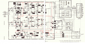
You need to check some of the voltages using a different method...
I can see a lot of 'base-emitter' volt drops that are not making sense (unless the devices are all faulty).
Q107 with +39v on the base and -39v on the emitter. There are many other examples like that.
For an NPN device you will not see more than around 0.8 volts across the B-E junction. And you must measure across the device for accuracy. The base will always be the more positive.
For a PNP its exactly the same except now the emitter is the more positive of the two.
If the polarity was wrong due to a circuit problem then the reverse voltage would be some indeterminate value but probably not exceeding around 7 or 8 volts.
True that, was yesterday evening.
I tested all transistors with the diode test today but alle had B-E B-C values about 0,6V-0,9V.
The filter cap is totally over and i dont want to power the amp up with them anymore.
Yeah good idea I will do that with the new capacitors and with some more electrical equipment.
Then i will measure the voltage direcly over the transistor pins and maybe this will brin light into the darkness.
- Status
- This old topic is closed. If you want to reopen this topic, contact a moderator using the "Report Post" button.