Hi,
I am working on upgrading an Adcom GFA-555 (mkI). I noticed there are quite a few old posts on this amp and I enjoyed reading them.
Based on this I would like to do the following:
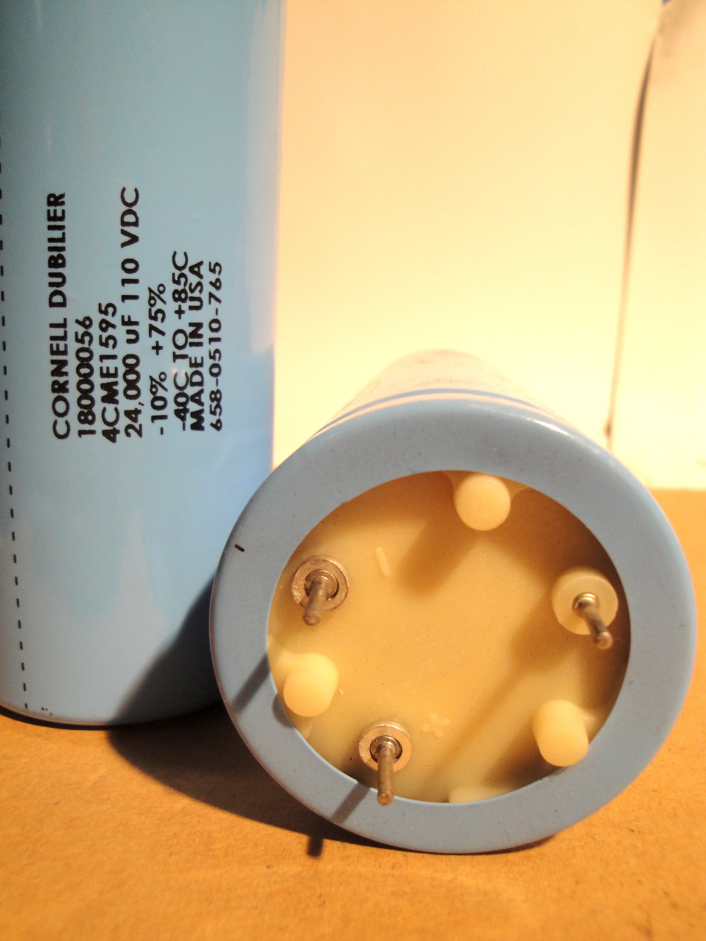
- Recap the amp with fresh electrolytic capacitors. Nichicon Ultra Fine Gold caps for the input board. Apexjr 24.000uf 110V computer grade caps for filter caps.
- Fix the DC offset imbalance by adding a second 33.2r RN55D resistor per channel, this will go in place of the jumper next to R3 on the input PCB. I will also add a 1K trimmer between the emitters of Q1/2, and connect the wiper to the junction of the two 33.2r resistors to fine tune the DC offset.
- Increase the feedback resistor R6 to 33.1K RN55D
- Replace the ceramic 68pF capacitors (C8, C9) with silver mica 68pF 500V ones
- Replace the driver transistors Q11 and Q12, currently D525 and B595 (2sb595 and 2sd525?) with MJE15030/31
- replace the glass fuses for ceramic fuses
The power supply: I understand the 700VA 52-0-52VAC power transformer is not up to the task, and should be beefed up. Can I add a 800VA 55-0-55VAC toroid, place it in parallel to the existing toroid secondary, and combine the AC outputs at the bridge rectifier? Or am I better off building two separate power supplies, one per channel?
Overall, does the above sound like a good approach?
I am working on upgrading an Adcom GFA-555 (mkI). I noticed there are quite a few old posts on this amp and I enjoyed reading them.
Based on this I would like to do the following:
- Recap the amp with fresh electrolytic capacitors. Nichicon Ultra Fine Gold caps for the input board. Apexjr 24.000uf 110V computer grade caps for filter caps.
- Fix the DC offset imbalance by adding a second 33.2r RN55D resistor per channel, this will go in place of the jumper next to R3 on the input PCB. I will also add a 1K trimmer between the emitters of Q1/2, and connect the wiper to the junction of the two 33.2r resistors to fine tune the DC offset.
- Increase the feedback resistor R6 to 33.1K RN55D
- Replace the ceramic 68pF capacitors (C8, C9) with silver mica 68pF 500V ones
- Replace the driver transistors Q11 and Q12, currently D525 and B595 (2sb595 and 2sd525?) with MJE15030/31
- replace the glass fuses for ceramic fuses
The power supply: I understand the 700VA 52-0-52VAC power transformer is not up to the task, and should be beefed up. Can I add a 800VA 55-0-55VAC toroid, place it in parallel to the existing toroid secondary, and combine the AC outputs at the bridge rectifier? Or am I better off building two separate power supplies, one per channel?
Overall, does the above sound like a good approach?
Hi, I'm looking for input on my proposed mods. I'm hoping to learn from the more experienced people here, maybe they can give me some input. The proposed mods really are things I am considering based on what I have read, nothing more.
I noticed the amp sounds somewhat distorted in the upper mids and top end. There was quite a bit of DC Offset: about 20 and 45mV.
Since then the following was done:
- replaced the 4.7uF and 47uF electrolytic caps on the PCB with Nichicon Fine Gold caps.
- removed dust, cleaned contacts, cleaned fuses.
- Set bias to 20mA after 20 minutes of warm up.
- added 22uf 160 uF nichicons to the old ecaps.
- addressed the DC offset by adding a 33.2r resistor to the emitter of Q2 and a 1K trimmer between the emitters of Q1/2 and the wiper to the junction of the 33.2r resistors. With that I was able to set the DC offset to 1 and 2.5mV. On the 2.5mV side I had to turn the trimmer all the way.
Did not change the driver transistors yet. Currently it has D525 and B595 (2sb595 and 2sd525?). I ordered replacement MJE15030/31, and measured hfe with a multimeter: 87, 109 / 363, 379. Did not measure Vbe yet. That seems way off. Since it will be in an emitter follower, do I need to worry about this?
The amp sounds very similar but the grain/distortion is still there. My guess is that Q1/2 need to be matched, and same for Q9/10?
Anyone ever dealt with removing the grain from a GFA555?
The schematic can be seen here: http://akdatabase.org/AKview/albums/userpics/10007/Adcom GFA-555 Service Manual.pdf
Thanks!
I noticed the amp sounds somewhat distorted in the upper mids and top end.
If so, it needs to be repaired. ALWAYS get a unit working properly first before trying to modify it. Never modify unless you understand a circuit as well as the designer.
anatech is our local expert on Adcom repairs, and may have some suggestions on troubleshooting.
If so, it needs to be repaired. ALWAYS get a unit working properly first before trying to modify it.
I agree, which is why I held off after partially restoring it.
anatech is our local expert on Adcom repairs, and may have some suggestions on troubleshooting.
I have read some of his posts in other Adcom GFA 555 threads. He seems very knowledgeable. I am sure there are others that have valuable insights as well.
Hi Jelle,
Yes, get it working properly first. You might have very low bias current. Follow the service manual and check everything out that way first. The service manual is always the best place to start.
I really do not agree with massive capacitance. It creates other issues as well. There is seldom a free lunch when redesigning an amplifier. I have personally never seen any improvement from increased capacitance on instruments or through listening. Try and keep it as stock as you can when starting your modifications. There is no sense in creating issues to chase around in addition to any improvements.
Best place to start. Match the input pair (Diff pair, long tailed pair) very closely. Look in the 565 thread for detailed information on that thing. As it turns out Robert Pease designed something very similar for himself I just found out. Is that cool or what?
-Chris
Hi Anatech, Yes, the bias current and the service manual, I looked into that and set the bias current at 20mV over the 0.82R emitter resistors, I let it stabilize for 20 minutes into a 8r 250W resistive load, and 560r resistors were placed from the input to ground. This was done to create the conditions as outlined in the manual. The manual calls for 16mV, but I had seen several people on this forum recommend 20mV, so I went with that.
I agree with getting it to work first, and for the mods that are being considered, these will be done in a way that I can always reverse it. And I will go step by step, and evaluate. Good points, thanks for that. I have designed and built an amp or two in my life, just never anything with transistors.
The DC offset was set to 1 and 2.5mV, see my previous post. It took quite the adjustment on the trimmer I added. Based on this I believe the differential pair is way off. Thanks for the pointer, I will look.")
Jelle
I agree with getting it to work first, and for the mods that are being considered, these will be done in a way that I can always reverse it. And I will go step by step, and evaluate. Good points, thanks for that. I have designed and built an amp or two in my life, just never anything with transistors.
The DC offset was set to 1 and 2.5mV, see my previous post. It took quite the adjustment on the trimmer I added. Based on this I believe the differential pair is way off. Thanks for the pointer, I will look.
Jelle
I am building the transistor test jig that Anatech pointed me to. This jig will be used to match transistors for Q1/2, the differential pair. The original parts are 2sc2240, but I cannot seem to find these through the usual vendors Mouser and Digikey. A number or transistors with the 2sc2240 part number are listed on ebay, but I am hesitant.
I did see that on this forum ksc1845 was mentioned as a replacement. Would that work in this position?
I did see that on this forum ksc1845 was mentioned as a replacement. Would that work in this position?
Update, whoever built this thing did not bother making sure the Collector on the drivers would have a decent electrical connection.
When replacing the driver transistors Q11 and Q12, originally D525 and B595 (2sb595 and 2sd525?) with MJE15030/3, I noticed there was electrically insulating thermal paste under the washer/bolt holding the Collector down (that also serves to holds the transistor down onto the heat sink). Not sure what did what, whether it was the transistor change or restoring the electrical contact, but the top end sounds clear now.
On to the differential pair. Original replacements are ordered.
Hi Jelle,
Yes, 2SD525 and 2SB595 that were selected for high voltage breakdown. Your replacements should be fine.
The thermal compound around the screw was not likely a problem. Under pressure you would have had good electrical contact with the bottom of the PCB anyway. Looks like it needed those transistors replaced after all. I'm glad you were able to find some replacement transistors for the diff pair.
-Chris
Question Jelle -
In posts 1 & 4, you mention replacing Q11 & Q12 with MJE15030/1
In post 10, you mentioned using MJE15030/3, and anatech said that those were OK.
Q: Was post 10 a typo? Mouser has 28/29, 30/31 & 32/33 parts available (differing in max voltage and how they measure hfe), so I'm somewhat confused about the proper repacement pairing would be. What is the most important spec to try to match?
Hi MINUX75,
You can be certain that any parts a manufacturer has installed are generally important. In this case, those parts are a low pass filter to keep RF out of the amplifier. The stability of the amplifier may also be compromised without that impedance on the input.
I think your improvement in sound quality was a case of expectation bias. Your advice is poorly conceived and not recommended.
-Chris
Ahhhh, no! Don't do that.If you want an improved sound for a small amount of work, you can remove R1,C1
You can be certain that any parts a manufacturer has installed are generally important. In this case, those parts are a low pass filter to keep RF out of the amplifier. The stability of the amplifier may also be compromised without that impedance on the input.
I think your improvement in sound quality was a case of expectation bias. Your advice is poorly conceived and not recommended.
-Chris
no coil no base stoppers resistors?
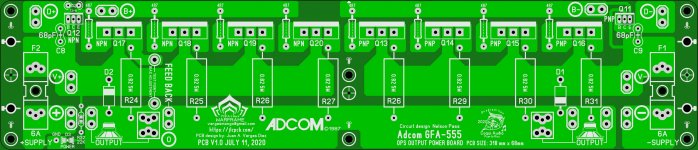
hi guys I'm making a clone of the Adcom GFA-555 I notice that the design does not have a output coil and no base stoppers? I was thinking to add it to the PCB is it necessary or not? musty the air coil got me thinking
hi guys I'm making a clone of the Adcom GFA-555 I notice that the design does not have a output coil and no base stoppers? I was thinking to add it to the PCB is it necessary or not? musty the air coil got me thinking
Attachments
- Status
- This old topic is closed. If you want to reopen this topic, contact a moderator using the "Report Post" button.
- Home
- Amplifiers
- Solid State
- Upgrading an Adcom GFA-555...