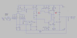
I'm building an AMP I put together and I have some questions that I can't figure out by myself. The detail is in the attache image, and I measured the voltage across point A and B, and got it logged for 20 minutes while nothing is connected to the AMP and idle. Both drivers was monted on the same heat sink, while the pre drivers are on top of the drivers so they are thermally coupled as close as physically possible.
The idea is that the Vbe of pre driver and driver will cancel with each other and leave the Vbe multiplier generate only 2 Vbe to bias the out transistors, and mount the bias transistor on top of the out transistor, you get great Bias stability.
However, I can see the Vab increases over time when the temp get higher, and simulation says the same thing. So actually there won't be 100% cancel each other and left around 60mV which will increase with tempture even though they are tightly thermally coupled. This leads the final bias current drifted around and I can't accurately set the bias, especially when the current is at the high end, let's say 200ma per device, and extreme case will be with a small heatsink for the out transistors. I sometime got thermall runnaway in my prototype, but that is another story.
Anyone have any experience with the diamond buffer driver triple, please?
Thanks!
Richard
Attachments
This is a another cross connection variant topology .
This is a similar schematic Mosfet400 full simetric => Proiect public - Pagin? 24 - Amplificatoare - Forumul Electronistilor :
https://postimg.cc/image/4mgaaae3h/
Unfortunately it is a only my example MOS FET power ends , not yet a bipolar example , it is my conceptual cross connection , for a very good control a speed switch off and full control of power stage .
Can you imagine a similar scheme for bipolar final ...
Sorry of offtopic ... maybe helped anyone .
Sorry for my bad english .
Hi Boborich,
Are you sure it's not oscillating in some way?
From my perspective, at a first glance, your design should be thermally stable. If there's no some local oscillation in the OPS.
See my design VHex+BT for example. The drivers are in the similar configuration as your pre-drivers, placed on the main heatsink, together with the output devices (well, those are the HexFETs). This configuration was working almost perfectly even with no bias spreader, except when it ran at high power for a long time and the heatsink became really hot - there was still no runaway, but the quiescent current increased, going back very slowly. That's the reason I have added a "supplementary" low-sensitivity bias spreader.
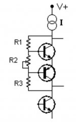
If the situation is as you describe and there's noboscillation observed, you can use more sensitive 2-transistor configuration for the bias spreader (npn + pnp).
See the picture attached - not a good drawing, but you get the idea. CFP spreader configuration is the other option, also rather high-sensitivity one.
Cheers,
Valery
Are you sure it's not oscillating in some way?
From my perspective, at a first glance, your design should be thermally stable. If there's no some local oscillation in the OPS.
See my design VHex+BT for example. The drivers are in the similar configuration as your pre-drivers, placed on the main heatsink, together with the output devices (well, those are the HexFETs). This configuration was working almost perfectly even with no bias spreader, except when it ran at high power for a long time and the heatsink became really hot - there was still no runaway, but the quiescent current increased, going back very slowly. That's the reason I have added a "supplementary" low-sensitivity bias spreader.
If the situation is as you describe and there's noboscillation observed, you can use more sensitive 2-transistor configuration for the bias spreader (npn + pnp).
See the picture attached - not a good drawing, but you get the idea. CFP spreader configuration is the other option, also rather high-sensitivity one.
Cheers,
Valery
Attachments
This is a another cross connection variant topology .
This is a similar schematic Mosfet400 full simetric => Proiect public - Pagin? 24 - Amplificatoare - Forumul Electronistilor :
https://postimg.cc/image/4mgaaae3h/
Unfortunately it is a only my example MOS FET power ends , not yet a bipolar example , it is my conceptual cross connection , for a very good control a speed switch off and full control of power stage .
Can you imagine a similar scheme for bipolar final ...
Sorry of offtopic ... maybe helped anyone .
Sorry for my bad english .
Not sure whether I got your point, but thanks for the reply.
BR,
Richard
Hi Boborich,
Are you sure it's not oscillating in some way?
From my perspective, at a first glance, your design should be thermally stable. If there's no some local oscillation in the OPS.
See my design VHex+BT for example. The drivers are in the similar configuration as your pre-drivers, placed on the main heatsink, together with the output devices (well, those are the HexFETs). This configuration was working almost perfectly even with no bias spreader, except when it ran at high power for a long time and the heatsink became really hot - there was still no runaway, but the quiescent current increased, going back very slowly. That's the reason I have added a "supplementary" low-sensitivity bias spreader.
If the situation is as you describe and there's noboscillation observed, you can use more sensitive 2-transistor configuration for the bias spreader (npn + pnp).
See the picture attached - not a good drawing, but you get the idea. CFP spreader configuration is the other option, also rather high-sensitivity one.
Cheers,
Valery
Hi Valery,
Thanks for your kindness of sharing your knowledge. You helped me a lot last time when I was stuck in the FFT measurement a few weeks back. Really appreciate it!
I used a DS1054Z hacked to 100Mhz and there is no oscillation, this was my 1st thought. I'll try your recommendations and report back to this thread, just in case someone else go into my situation.
Thanks!
Richard
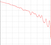
I did a log of Vq(across 2 REs with 0.1ohms each) just now for a cold start and looks like a thermal run away trend in 25 minutes sitting in idle.
The interesting thing is that looks like the Vbe multiplier is hotter than the OPS transistor by 10 degress. Oscillation of the Vbe multiplier?
Strange....
Richard
The interesting thing is that looks like the Vbe multiplier is hotter than the OPS transistor by 10 degress. Oscillation of the Vbe multiplier?
Strange....
Richard
Attachments
Hi Richard,
So, the quiescent current of the output stage goes down-down-down, then fluctuates a bit, then goes down again and immediately jumps to infinity?
That's weird. Something is not right...
What happens to the drivers? Does their temperature stay relatively constant?
So, the quiescent current of the output stage goes down-down-down, then fluctuates a bit, then goes down again and immediately jumps to infinity?
That's weird. Something is not right...
What happens to the drivers? Does their temperature stay relatively constant?
Hi Richard,
So, the quiescent current of the output stage goes down-down-down, then fluctuates a bit, then goes down again and immediately jumps to infinity?
That's weird. Something is not right...
What happens to the drivers? Does their temperature stay relatively constant?
Sorry, I didn't do the screen shot properly. It is negative voltage, so it actually goes up and fluctuates until a point it went up so quickally that I turned off the power...
Ah... I see
What I would do:
- Remove the output transistors, let the spreader transistor hang in the air;
- Split 47R at the drivers' emitters in 2 halves (24R x 2 will do), connect NFB resistor to that point;
- Switch the whole thing on, measuring the voltage between the drivers' emitters.
See if the spreader transistor is heating up by itself. I should not be the case.
If everything looks fine, try to heat the spreader - see what happens to the voltage between the drivers' emitters. It has to work reliably - higher temperature -> lower voltage and vice versa.
Last point - if everything looks fine, try the higher value the the output transistors' emitters. 0R22 is a good well-tested value.
Let me know how it goes - interesting issue
Cheers,
Valery
Ah... I see
What I would do:
- Remove the output transistors, let the spreader transistor hang in the air;
- Split 47R at the drivers' emitters in 2 halves (24R x 2 will do), connect NFB resistor to that point;
- Switch the whole thing on, measuring the voltage between the drivers' emitters.
See if the spreader transistor is heating up by itself. I should not be the case.
If everything looks fine, try to heat the spreader - see what happens to the voltage between the drivers' emitters. It has to work reliably - higher temperature -> lower voltage and vice versa.
Last point - if everything looks fine, try the higher value the the output transistors' emitters. 0R22 is a good well-tested value.
Let me know how it goes - interesting issue
Cheers,
Valery
Here comes the updates:
1. The spreader doens't heat up by itself.
2. The spreader do work as designed when heated up using a heatgun, the spreader voltage decreases.
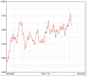
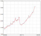
3. If I bias the OPS with 50mA current, it seem to work just fine, is it? Check the screen shot below.
4. If I bias it at 100mA current, there seems to be an issue. Check the other screen shot below.
Note the Y axis is mV, and the X axis is time in minutes.
Will do more test tomorrow.
Looks like I got a small heatsink, do I?
BR,
Richard
Attachments
Hi Valery,
Thank you very much for the suggestions! I have finished all the debug and the amp is running like a charm. The issue is actually the heatsink being too small. The heatsink is for test purpose so that I can flip the board easily to find what is cauing the oscillation. I install the whole thing to a proper heatsink the issue went away, so it is thermal run away (1st time experience with it). After that I found the oscillation was caused by the VAS, and a 22pf B-C cap fixed it.
Again, thank you for your reply.
BR,
Richard
Ah... I see
What I would do:
- Remove the output transistors, let the spreader transistor hang in the air;
- Split 47R at the drivers' emitters in 2 halves (24R x 2 will do), connect NFB resistor to that point;
- Switch the whole thing on, measuring the voltage between the drivers' emitters.
See if the spreader transistor is heating up by itself. I should not be the case.
If everything looks fine, try to heat the spreader - see what happens to the voltage between the drivers' emitters. It has to work reliably - higher temperature -> lower voltage and vice versa.
Last point - if everything looks fine, try the higher value the the output transistors' emitters. 0R22 is a good well-tested value.
Let me know how it goes - interesting issue
Cheers,
Valery
- Status
- This old topic is closed. If you want to reopen this topic, contact a moderator using the "Report Post" button.
- Home
- Amplifiers
- Solid State
- Diamond buffer driver triple OPS bias stability