Not sure if this is the best place to ask this, but might as well try.
My car's main amplifier uses Toshiba TA8233H chips (3 of them to be exact). Upon looking at the datasheet, I discovered that one of the pins is a clip detector. I'd like to make use of this somehow, but I'm not exactly sure how to design it.
Here's a picture of the datasheet page describing how the clip detection pin works:

From what I've researched, this is how to use it:

The idea is if one (or more) of the three amp chips is clipping, an LED will turn on.
First question: will this circuit will work as described? If not, what do I need to change?
Second question: Is there a way I can sort of "buffer" the LED to stay lit for a second or two, even if the clipping signal is very brief? I'm concerned that I won't see the LED unless it's constantly clipping.
Thanks!
My car's main amplifier uses Toshiba TA8233H chips (3 of them to be exact). Upon looking at the datasheet, I discovered that one of the pins is a clip detector. I'd like to make use of this somehow, but I'm not exactly sure how to design it.
Here's a picture of the datasheet page describing how the clip detection pin works:
From what I've researched, this is how to use it:
The idea is if one (or more) of the three amp chips is clipping, an LED will turn on.
First question: will this circuit will work as described? If not, what do I need to change?
Second question: Is there a way I can sort of "buffer" the LED to stay lit for a second or two, even if the clipping signal is very brief? I'm concerned that I won't see the LED unless it's constantly clipping.
Thanks!
That looks workable. Being open collector should mean that no diode gating is needed as there should be no interaction between the chips. Each can pull the transistor base down when a clipping event occurs.
Only practical comment is that 120 ohms feeding a modern high brightness LED could be much too bright, however clipping is by its nature is often short lived, perhaps only lasting a few milliseconds. So what you really need is something like a 555 timer chip configured as a monostable to drive the LED. That would stretch the clipping events and illuminate the LED for say 1 second at a time.
Only practical comment is that 120 ohms feeding a modern high brightness LED could be much too bright, however clipping is by its nature is often short lived, perhaps only lasting a few milliseconds. So what you really need is something like a 555 timer chip configured as a monostable to drive the LED. That would stretch the clipping events and illuminate the LED for say 1 second at a time.
Ah yes, 240 ohms would probably be a better choice.That looks workable. Being open collector should mean that no diode gating is needed as there should be no interaction between the chips. Each can pull the transistor base down when a clipping event occurs.
Only practical comment is that 120 ohms feeding a modern high brightness LED could be much too bright
Hmm. Any chance some transistors and capacitors could be used instead of a 555? I've got plenty of those in my bin, but no 555s. I could order one of course, I just prefer to recycle.however clipping is by its nature is often short lived, perhaps only lasting a few milliseconds. So what you really need is something like a 555 timer chip configured as a monostable to drive the LED. That would stretch the clipping events and illuminate the LED for say 1 second at a time.
")
Hmm. Any chance some transistors and capacitors could be used instead of a 555? I've got plenty of those in my bin, but no 555s. I could order one of course, I just prefer to recycle.
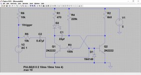
Of course. This shows a typical monostable.
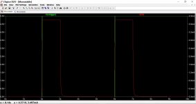
The part at the left (voltage source) is your open collector tied to 5 volts via R6. The monostable gives around a 1 second pulse each time it is triggered. The LED is run directly from the collector of Q1. Current is at the right side of the graph. Green trace is the spiky trigger signal that might only last a millisecond or so.
Attachments
- Status
- This old topic is closed. If you want to reopen this topic, contact a moderator using the "Report Post" button.