Cubie3 (class AB)
Cubie3
Cubie3
This project started few months ago when I found a nice R-core transformer in a pile of electro junk at the local flea-market (60V CT secondary, 200VA). With such a voltage/power rating the logical choice was 2 x 50W AB class amp. Lateral MOSFETs (connected as Source followers) were chosen as output devices this time too.
The input stage needs to provide more gain than in Cubie2 so I chose BA3-like topology with cascoded JFETs and current mirror load on them. Q5/Q8 still make a base-driven transconductance gain stage which enables GFB/NoGFB games. I chose the loop...
Do you have the USSA-5 schematic or can you point to it?
Amplificateur USSA-5 : evolution de la conception de la version 4
Use google translator as needed.
Fab
Amplificateur USSA-5 : evolution de la conception de la version 4
Use google translator as needed.
Fab
I have the USSA-5 board right here, thanks for the reminder, need to build it along with a host of other projects...
Best,
Anand.
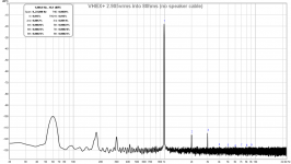
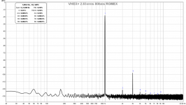
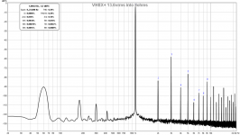
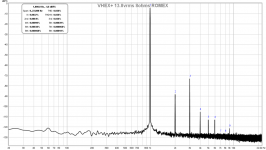
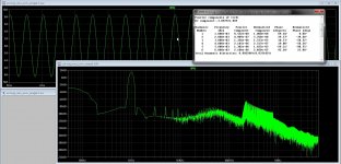
I have just measured one of my amps, the VHEX+ using a 8ohm dummy load. Uncovered a bit of a can of worms. It seems that the speaker cable DOES make a difference. I got rather high and strange looking FFT when load is connected at end of usual 16gauge stranded real copper cable (clear vinyl low cost zip cord). So I put the load directly on the amp’s banana jack output and distortion anomaly was gone. I then replaced the stranded speaker cable with solid copper 12gauge Romex (with unused solid copper ground in between positive and negative). Redid the measurement and got reduced distortion, reduced 60Hz mains hum pickup, but it’s not all good in that 3rd order harmonic distortion went up! So what’s going on? Probably changes in parasitic capacitance and inductance are feeding back into amp?
Subjectively the amp sounded more dynamic and clarity was higher with Romex but fatiguing. This is with my 10F/8424 RS225 transient perfect FAST speakers in B.B. cabinet.
At 13.8vrms there may be a mild oscillation going on as FFT peaks at higher orders varied a bit in time. Strange is the reduction of mains peaks in the signal with the Romex.
Attachments
Last edited:
A few questions
A couple of questions. When you were taking measurements with a cable connecting the load to the amplifier where did you take the measurement? Across the load or at the amplifier output?
The presence of a 60 HZ peak in FFT plots seem to indicate some possibility that your measuring equipment may be causing an earthing problem?
Did you look at the output waveforms on a CRO to look for parasitic oscillation? It may be in the order of MHz. You may need to increase the test tone amplitude so the output it near the maximum possible output amplitude.
Do you think these recent observations may have cause a rethink on the previous testing you have done with different amplifiers?
I have just measured one of my amps, the VHEX+ using a 8ohm dummy load.
A couple of questions. When you were taking measurements with a cable connecting the load to the amplifier where did you take the measurement? Across the load or at the amplifier output?
The presence of a 60 HZ peak in FFT plots seem to indicate some possibility that your measuring equipment may be causing an earthing problem?
Did you look at the output waveforms on a CRO to look for parasitic oscillation? It may be in the order of MHz. You may need to increase the test tone amplitude so the output it near the maximum possible output amplitude.
Do you think these recent observations may have cause a rethink on the previous testing you have done with different amplifiers?
Measurement is always across load resistor. Measuring equipment is laptop and Focusrite 2i4 powered via laptop battery not connected to mains. Previous measurements always had dummy load connected directly to amp. This time, amp was in place and had speaker cables connected so I thought to use the cables.
Have not had chance to look at signal with scope yet. I have a DSO, but it is pretty fast so should resolve oscillation, if any.
Have not had chance to look at signal with scope yet. I have a DSO, but it is pretty fast so should resolve oscillation, if any.
Last edited:
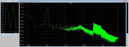
I have just measured one of my amps, the VHEX+ using a 8ohm dummy load. Uncovered a bit of a can of worms. It seems that the speaker cable DOES make a difference. I got rather high and strange looking FFT when load is connected at end of usual 16gauge stranded real copper cable (clear vinyl low cost zip cord). So I put the load directly on the amp’s banana jack output and distortion anomaly was gone. I then replaced the stranded speaker cable with solid copper 12gauge Romex (with unused solid copper ground in between positive and negative). Redid the measurement and got reduced distortion, reduced 60Hz mains hum pickup, but it’s not all good in that 3rd order harmonic distortion went up! So what’s going on? Probably changes in parasitic capacitance and inductance are feeding back into amp?
Subjectively the amp sounded more dynamic and clarity was higher with Romex but fatiguing. This is with my 10F/8424 RS225 transient perfect FAST speakers in B.B. cabinet.
At 13.8vrms there may be a mild oscillation going on as FFT peaks at higher orders varied a bit in time. Strange is the reduction of mains peaks in the signal with the Romex.
Hi X
Long time not see, everything oke? here fine, but have coldwave here now and -5 on daytimes with -20 chilltemp, for so late in year quite rare, warming? yes that is cause..
Last two pics looks nasty, something with cables, or is the amp balanced? I see your shop has also dutch? language, or maybe your shop is on a special site.
I have been busy with class D amps, I do not now if I do go on with the circlotron, I did even think on a class D circlotron, do not excists, then no need for deadtime and such.
regards
Attachments
Hi Kees,
Good to hear from you. Been busy with ALPHA amp lately and making speakers In wood. Etsy figures out your locality based on IP address and adjusts language accordingly is my guess. I always assumed shop was in English but I guess not! Your FFTs are for your own class d amp?
The amp above is the VHEX+ (a great amp and one of my reference amps) by vzaichenko. It’s push pull Class AB with current drive topology. More on this thread:
IRFP240/9240 Amplifier (simulated on TINA)
The FFT are indeed mine class d amp, a UCD version with two feedback loops, it is delta sigma like modulator, I have another with current feedback loop and voltage.
I was and am curious how the amp sound, but I like openloop more, maybe try that first with oil capacitor and air coil als low pass filter without feedback, air coils are lineair, but more EMI,, so use a 24dB filter and see what happens.
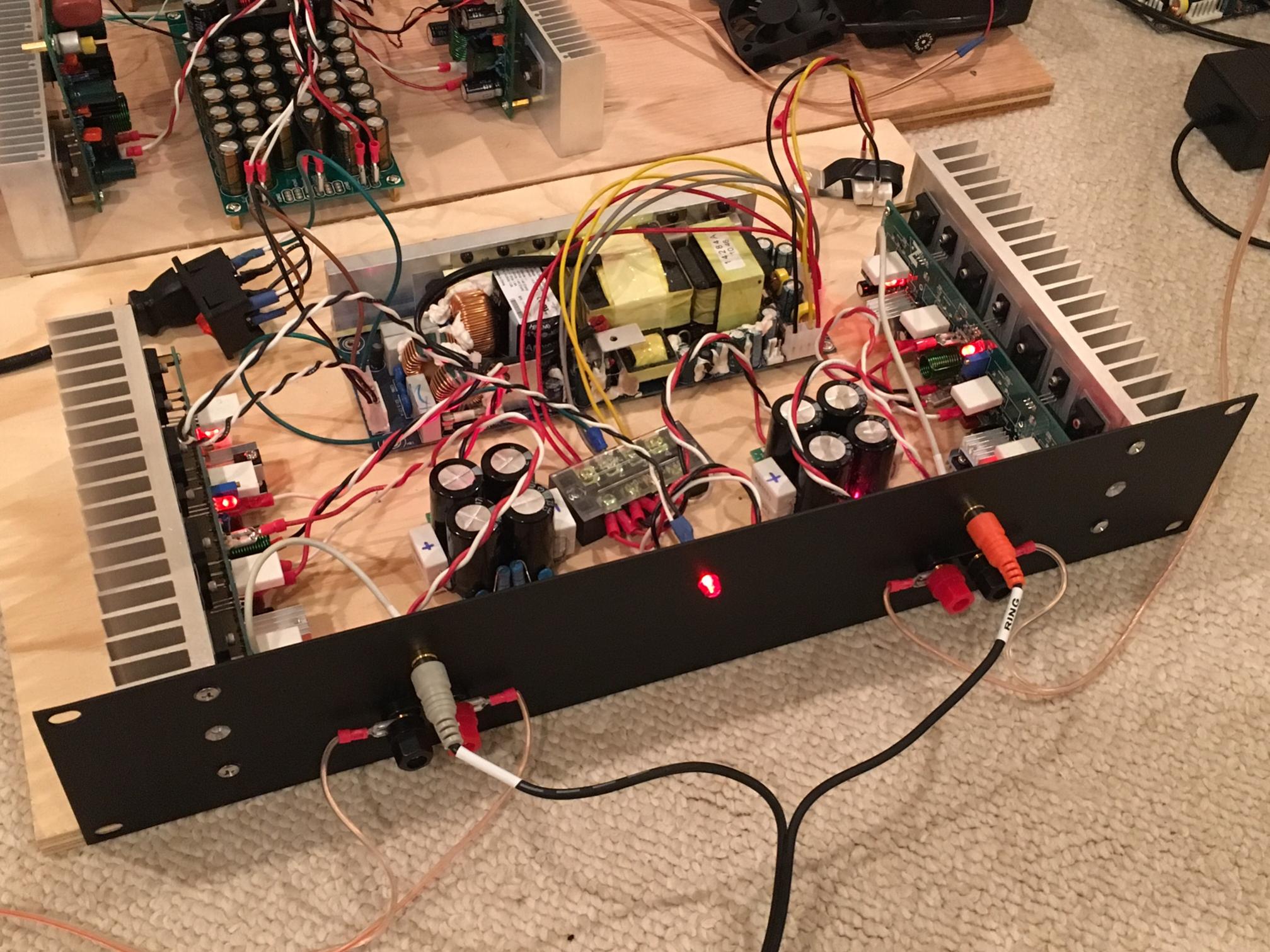
Looks good that photo of yours, I see a SMPS? I do build this myself, I have the transformers, I do soft switcher resonant, give a sinusoidal output and as such less harmonic content, and fast regulator, here a sawtooth or triangular with a comparator, that do regulate fast.
Mine pictures you see uneven harmonics only, and I think this is even by simulation or comparator behavior and maybe not present in real that way, but building it will tell.
regards
I was and am curious how the amp sound, but I like openloop more, maybe try that first with oil capacitor and air coil als low pass filter without feedback, air coils are lineair, but more EMI,, so use a 24dB filter and see what happens.
Looks good that photo of yours, I see a SMPS? I do build this myself, I have the transformers, I do soft switcher resonant, give a sinusoidal output and as such less harmonic content, and fast regulator, here a sawtooth or triangular with a comparator, that do regulate fast.
Mine pictures you see uneven harmonics only, and I think this is even by simulation or comparator behavior and maybe not present in real that way, but building it will tell.
regards
Last edited:
Yes, that’s the Abletec 450w +/-53v SMPS that was on sale for $20 for a while. Nice unit - very low noise and well built - made in Europe.
Abletec 53v Dual Rail 450W Supply for $20
Abletec 53v Dual Rail 450W Supply for $20
Yes, that’s the Abletec 450w +/-53v SMPS that was on sale for $20 for a while. Nice unit - very low noise and well built - made in Europe.
Abletec 53v Dual Rail 450W Supply for $20
Can not built that myself for this mony. But these are to light for mine purposes, I do make high power, so 2x 80 volts 15 amps or so. For your amps thse are fine supplys.
regards
Last edited:
computer heat sink isn't suitable for amplifier
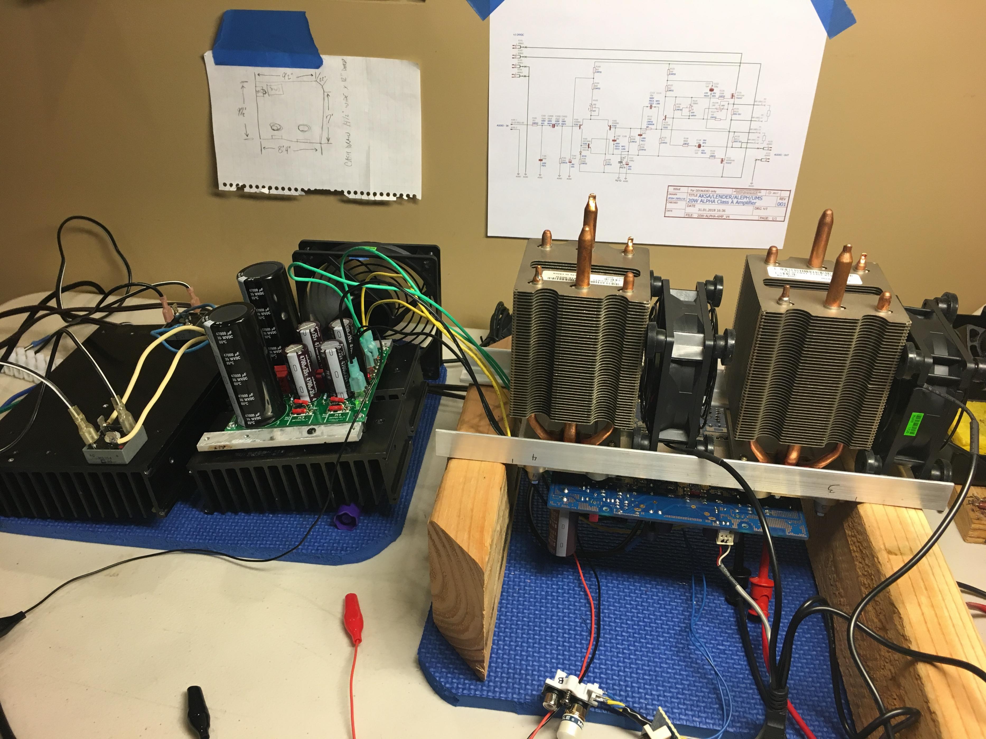
Why? If copper pad supports MOSFET heat pad and wattage rating (with fan) supports heat load, should be fine. That's what we are doing with ALPHA amp.
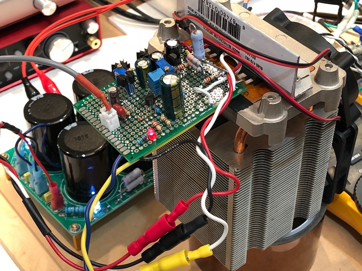
Here was my ALPHA 20 prototype with CPU cooler:
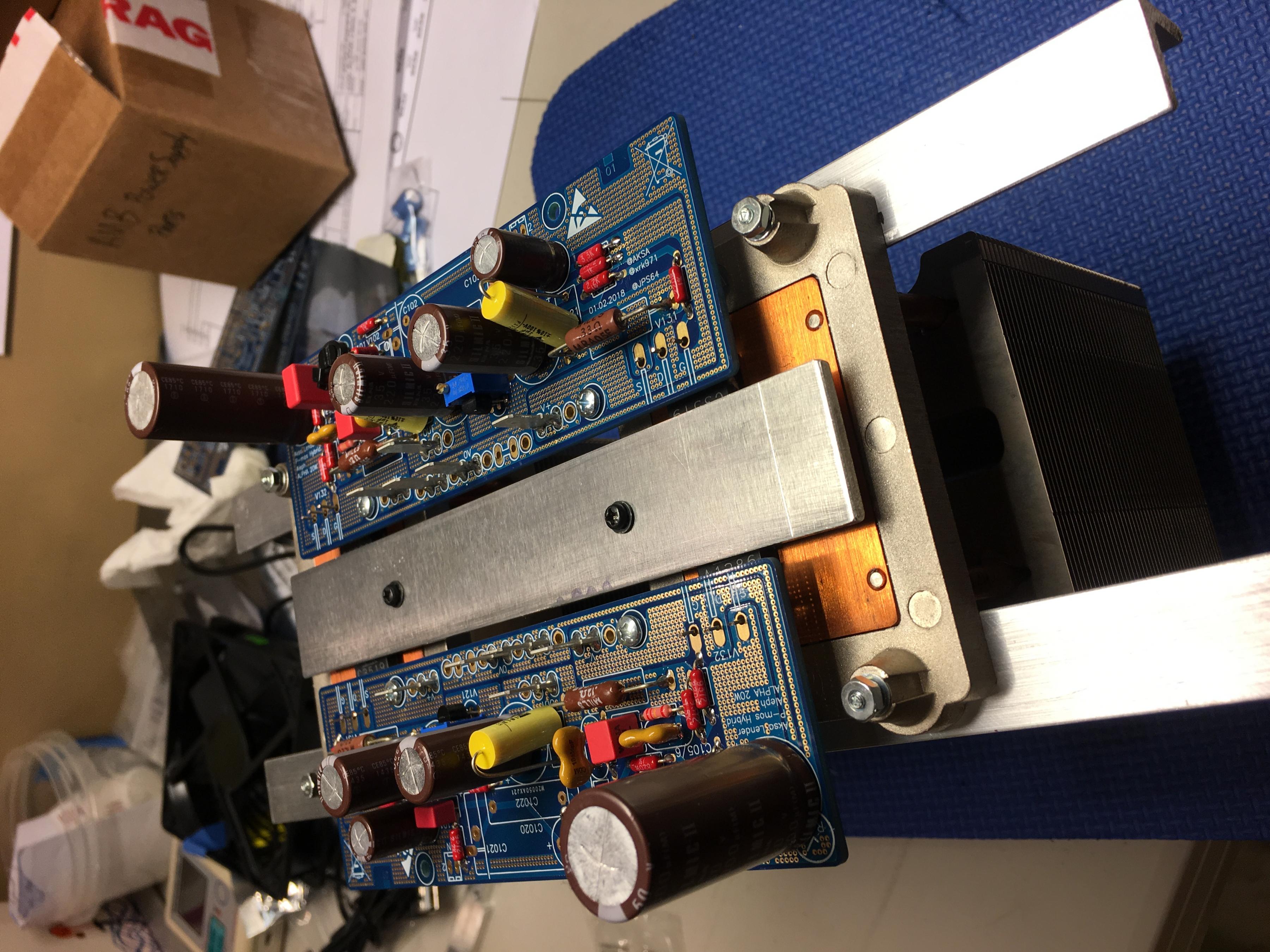
Here is Vunce's ALPHA 20, running happily with two Dell CPU heatpipe based heatsinks:
Here is view of underside where MOSFETs are clamped:
Many Intel CPUs routinely put out 120w - hence the need for heatpipes and fan. No passive heatsink could remove heat from a small area that fast.
Anyhow, works very well, is compact and low cost relative to massive aluminum heatsinks. We will be adding safety temp auto shutdown to the 52W Alpha which is dissipating 100W per MOSFET (4 CPU coolers total for 400W dissipation for stereo).
Last edited:
Why? If copper pad supports MOSFET heat pad and wattage rating (with fan) supports heat load, should be fine. That's what we are doing with ALPHA amp.
Here was my ALPHA 20 prototype with CPU cooler:
Here is Vunce's ALPHA 20, running happily with two Dell CPU heatpipe based heatsinks:
Here is view of underside where MOSFETs are clamped:
Many Intel CPUs routinely put out 120w - hence the need for heatpipes and fan. No passive heatsink could remove heat from a small area that fast.
Anyhow, works very well, is compact and low cost relative to massive aluminum heatsinks. We will be adding safety temp auto shutdown to the 52W Alpha which is dissipating 100W per MOSFET (4 CPU coolers total for 400W dissipation for stereo).
Because of airflow.. Ribs on PC heat sink are close to each other
- Status
- This old topic is closed. If you want to reopen this topic, contact a moderator using the "Report Post" button.
- Home
- Amplifiers
- Solid State
- Virtual Audition of Very Simple Quasi MOSFET Amp