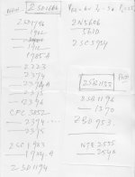
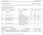
I'm a Class A newbie enthusiast and was looking for some simple approach, both in single ended or push-pull design. Of late digging some obscure corners, found this design. The first site owner claims to make so many amp though is silent about the source or anything. The second one shows a completed view but with Russian equivalent transistors of western ones. The original designs have Sanyo transistors 2SD1666 & 2SB1133 what I can not get here. The Russian equivalents translate into AD142 and BD720 or BD723. The original Sanyo ones have Veb=6v, Ic=3A, Pc=25W. But the replacements have very high values. Can I safely use the above ones? Though I found exact replacements of Sanyos from alltransistors in the second attached image. Kindly assist.
Circuits
Òåõíè÷åñêèé ôîðóì - Ïîêàçàòü ñîîáùåíèå îòäåëüíî - 5-âàòòíûé óñèëèòåëü íà òðàíçèñòîðàõ
Circuits
Òåõíè÷åñêèé ôîðóì - Ïîêàçàòü ñîîáùåíèå îòäåëüíî - 5-âàòòíûé óñèëèòåëü íà òðàíçèñòîðàõ
Attachments
The BD677 is a Darlington device. You could make that from two individual devices if needed. The outputs can be any common device such as TIP41 and TIP42 or TIP3055 and TIP2955. (AD142 is germanium... no good for this)
The circuit is very generic in nature and pretty much anything (suitably rated) will work.
The circuit is very generic in nature and pretty much anything (suitably rated) will work.
There is absolutely nothing on that page I would consider building. I will point out one of very bad things with this design. The fact that in order to get the output voltage close to where it should be requires around 50mA through the 330 ohm resistor at top. Consider the 1n4148 is a 10mA part. Even if the current is split with say 20mA into each output transistor and 10mA for the bd677, the 1n4148 is still passing 3 times it's rated current. Can you say magic smoke? I would avoid that page and the designs contained there in like the plague. But if you feel the need a direct equivalent for the 2sd1666/2sb1133 are the tip31a/tip32a.
Consider the 1n4148 is a 10mA part...
I think its a little bit more than that
")
The 4148 is rated at 200ma continuous current as long as it is kept at <25C. Even at 100C it is rated for >100ma
I think its a little bit more than that
The 4148 is rated at 200ma continuous current as long as it is kept at <25C. Even at 100C it is rated for >100ma
Quite right, thats what I get for looking too quickly, at the wrong page no less. Sorry for the misinformation, however, I still would not consider anything from that site as a useful build.
Attachments
Life itself is an assignment, we are just players!Why would you build that? Is it for a high school assignment? In the 60s?
Some prefer making Jean Hiraga l'monstre as their first, some, like me prefer the above one?
Zen is a cliche word now, so many are chanting the same. Just got curious about the class A amp version of 'zen' and found what is real zen is actually all about here indexHi, awful design, search on "Death of Zen". rgds, sreten.
anyway, what made the design awful?
Great! Once I get the replacement transistors this week, I'll do the same.Out of curiosity I shall simulate your amp.
Are we taking bets on whether it will work straight out of the box
No point of betting, mate. We are not going to loose anything other than few dimes!
And what if it would work? The schematic, images are so confidently made.
Someone has made it working.
And what if it would work? The schematic, images are so confidently made.
Someone has made it working.
That's because idiots tend to think they're really smart.
4 Types of Person (a guide to stupidity) (secretGeek.net)
https://en.m.wikipedia.org/wiki/Dunning–Kruger_effect
Last edited:
Life itself is an assignment, we are just players!
Some prefer making Jean Hiraga l'monstre as their first, some, like me prefer the above one?
But itá`s very poor design, to boot uncompensated and without a Zobel, it might "work" in simulation and get crazy when connected to a real world speaker.
Pictures show a very crude "kitchen table" construction, 2 inches away from a tiny speaker, doubt builder will notice it´s oscillating by the way.
To boot not only you can`t get the original transistors , but your equivalence table is very wrong, if it suggests a Germanium transitor instead of a visibly Silicon one.
Unless you believe in the Germanium era they packaged them in plastic TO220 cases or had NPN Darlingtons, among other details.
As said above, RUN!!! from designs in that page.
It makes even Red Circuits look sophisticated by comparison
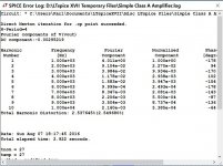
It is very doubtful that the circuit will oscillate. There is no frequency compensation because it doesn't need any. One inverting gain stage (that isn't particularly high gain - consider the low collector resistance) and a one-stage emitter follower? I would seriously doubt the ability of it to oscillate unless you put a few feet of wire in the supply leads. You need loop gain to oscillate, and there just isn't much there. That also means very little distortion correction as well. A few % distortion over its useable range would be par for the course. Might not sound awful, but won't be anything to write home about.
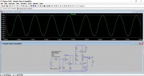
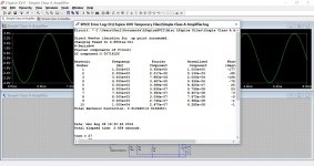
Great! Feels so nice you did the simulation. Yes, 2.5% is quite a high sum, but I've seen designs with 1% distortion. So with our tiny design, we can focus on polishing the design a little bit. Can it be bettered with tips from this great page?So...
Distortion is nearly 3% at maximum output. Maximum output is only -/+7.5 volts or so which is quite a poor efficiency. At 1 watt rms into 8 ohms the distortion is still over 2.5%
index
I hope so.
And I must say, you're the most optimistic and positive fellow here! A true designer's virtue. Keep it up.
Some say Harry Truman was an idiot, some say he was smart! (Remember tomorrow's date, can't be more timely irony for your lead! )That's because idiots tend to think they're really smart.
4 Types of Person (a guide to stupidity) (secretGeek.net)
https://en.m.wikipedia.org/wiki/Dunning–Kruger_effect
Great! Feels so nice you did the simulation. Yes, 2.5% is quite a high sum, but I've seen designs with 1% distortion. So with our tiny design, we can focus on polishing the design a little bit. Can it be bettered with tips from this great page?
index
I hope so.
And I must say, you're the most optimistic and positive fellow here! A true designer's virtue. Keep it up.
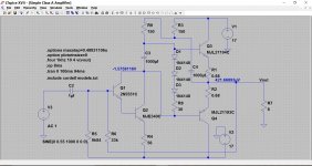
There are a couple of things we can do to try and improve it.
1/ You will have to adjust the current in the output stage by trial and error as it is very device dependent. In simulation it really needs 3 diodes in series, and the emitter resistors reducing to get the best performance. Adding a 100 ohm preset in series with the diodes might be an option, just check that the wiper of the preset is rated for at least 50ma or so.
2/ The diode chain should be bypassed with a large electrolytic. Doing that alone reduces the distortion dramatically.
3/ I've added a bootstrap arrangement which improves the maximum output level attainable by quite some margin.
Attachments
Great improvement! What could be possible replacement for MJL21194C and its pair?There are a couple of things we can do to try and improve it.
1/ You will have to adjust the current in the output stage by trial and error as it is very device dependent. In simulation it really needs 3 diodes in series, and the emitter resistors reducing to get the best performance. Adding a 100 ohm preset in series with the diodes might be an option, just check that the wiper of the preset is rated for at least 50ma or so.
2/ The diode chain should be bypassed with a large electrolytic. Doing that alone reduces the distortion dramatically.
3/ I've added a bootstrap arrangement which improves the maximum output level attainable by quite some margin.
- Status
- This old topic is closed. If you want to reopen this topic, contact a moderator using the "Report Post" button.
- Home
- Amplifiers
- Solid State
- Replacement transistors for Class A amp