I assume the shipping & PayPal fees are the same for 2 pairs as they are for 1 pair?
If so, I'm good to go. 🙂
It should be good as two pairs is not too much heavier.
Thanks Marc, I totally missed those errors.
Reposting corrected gerber files of CFH7.
Those who downloaded sprint lay file rotate 4700uF capacitor on CFH7 ver1.07, CFH9 ver1.01, CFH9 ver1.02 layout. Move +ve and -ve sign to correct tab.
Hello sonal,
isn't there a shortage of all pins of the BD139 in your layout?
BR
Günni
454Casull - 4 boards
Rick G - 2 boards
Hajj - 4 boards
xrk971 - 2 boards
redarc12 - 2 boards
Unfortunately no longer need 4 boards, only 2.
454Casull - 2 boards
Rick G - 2 boards
Hajj - 4 boards
xrk971 - 2 boards
redarc12 - 2 boards
454Casull - 2 boards
Rick G - 2 boards
Hajj - 4 boards
xrk971 - 2 boards
redarc12 - 2 boards
Hello,
this is CFH9CX board ordered from Seed studio.The amp is powered with +-48V DC,there is no heating. It play but with distortion on small volume. I can not get any bias current on power mosfets no mater what is bias pot position ,it has no effect on bias. All elements values are like in schematic in post 962 . What i can do to solve the problem with bias?
Regards
zoky2
Attachments


This is Thiagomogi's board, and I have not yet built it so cannot say whether or not it's proven - perhaps Thiagomogi can help if he has made one already?
Usually in a case of very low or no bias current that is un-responsive to pot adjustment, there is a bad connection somewhere (cold solder joint), or a gross error in reading a resistor value (like by 1000x) that is preventing the Vbe multiplier from providing the bias to the gates of the MOSFETs. Even if the front end was completely disconnected, the bias and outputs should warm up and be responsive to pot adjustment.
So double check and touch up solder joints leading to and around the middle BD139. Double check your resistor values around te Vbe multiplier, make sure the trimpot is not bad.
What voltages do you measure at pin 1 of the gates of MOSFET? What is voltage drop across the two 0.47R source resistors? What are the voltages on the 3 pins of the BD139 Vbe multiplier?
Hallo,
some mesurement on my board:
mosfets IRFP240 gate 2,72 V
mosfets IRFP 9124 gate 1,85 V
voltage drop across 0,47R resistors is 0 mv
BD139 E 2,1V
C 2,7V
B 2,2V
Trimer for bias is 1kohm multiturn
All voltage are referred to gnd, power supplay is +-47V dc.
Regards
zoky2
some mesurement on my board:
mosfets IRFP240 gate 2,72 V
mosfets IRFP 9124 gate 1,85 V
voltage drop across 0,47R resistors is 0 mv
BD139 E 2,1V
C 2,7V
B 2,2V
Trimer for bias is 1kohm multiturn
All voltage are referred to gnd, power supplay is +-47V dc.
Regards
zoky2
I have different measures.
VBE BD139
Base - GND = 2.84V
Collector - GND = 4.07V
Emitter - GND = 3,48V
BC546 input
Collector - GND = 41.91V
Emitter - GND = 700mV
BC556 input
Collector - GND = 42,11V
Emitter - GND = 614mV
Gate tension
Gate irfp9140 = 3.48V
Gate ifp240 = 4.07V
VBE BD139
Base - GND = 2.84V
Collector - GND = 4.07V
Emitter - GND = 3,48V
BC546 input
Collector - GND = 41.91V
Emitter - GND = 700mV
BC556 input
Collector - GND = 42,11V
Emitter - GND = 614mV
Gate tension
Gate irfp9140 = 3.48V
Gate ifp240 = 4.07V
When you take measurements in the output section, use the speaker output for the reference lead on your meter (the black one). Then the readings will be more stable and they will make more sense.
Try this again please.
-Chris
Try this again please.
-Chris
I have different measures.
VBE BD139
Base - GND = 2.84V
Collector - GND = 4.07V
Emitter - GND = 3,48V
BC546 input
Collector - GND = 41.91V
Emitter - GND = 700mV
BC556 input
Collector - GND = 42,11V
Emitter - GND = 614mV
Gate tension
Gate irfp9140 = 3.48V
Gate ifp240 = 4.07V
Hi Thiagomogi,
Good to know that the layout and PCB as posted works!
Thanks,
X
Hallo,
the problem with bias is solved, it was the wrong value trimer ,1kohm instead of 2kohm.There is some differences between schematic and silk screen value,so I was putting 1kohm trimer like on silk screen. I have not any 2kohm trimer so I build in 5kohm trimer and now everything is OK. The amplifier play very well, just the gain is a little low for full output from my PC. With CD player everything is very good,full of power and good sound.
regards
zoky2

You mean have BJTs for the outputs? Is there a particular reason you would rather have BJTs? It would be a complete redesign - so maybe someone can take a crack at it. I don't have the time at present with all my other projects going.
yes, bjt.
no particular reason other than curious as to how it sound different because outputs have their own distortion profile, and bjt is generally said to have 'more' bass due to higher transconductance.
and also i have extra 2sc5200/1943 pairs laying around. 🙂
no particular reason other than curious as to how it sound different because outputs have their own distortion profile, and bjt is generally said to have 'more' bass due to higher transconductance.
and also i have extra 2sc5200/1943 pairs laying around. 🙂
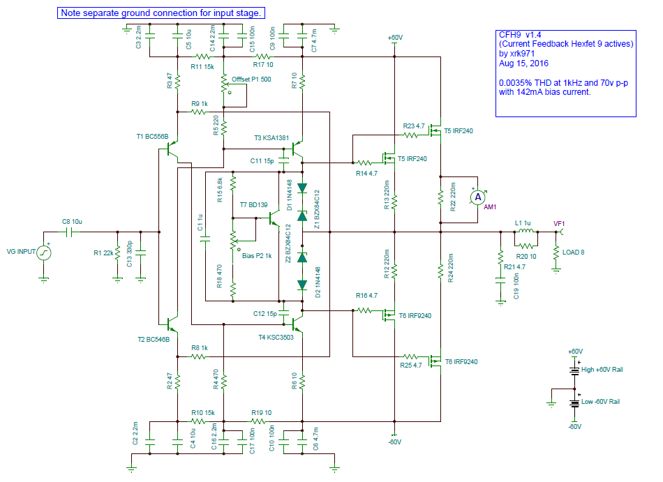
What do you guys think of 70v p-p output with 0.0035% THD at 1kHz? 60 volt rails required but layout looks like the F1 car design from Sonal just needs to be elongated to stuff another pair of cylinders to hot rod this ride.
We are probably right at the edge of the SOA as this is circa 300w. But for an extra $2 of MOSFETs, it sure is an exciting ride. 🙂
Schematic v1.04:
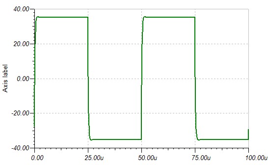
Square wave at 20kHz with 70v p-p:
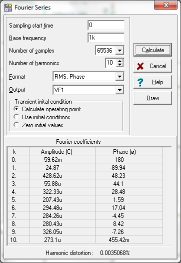
FFT analysis for distortion components, note that 2nd and 4th harmonic are dominant over 3rd and 5th so the sound should have a pleasant harmonic profile:
I work on amplifiers performance measurements with tina.Could you explain how we can measure these parameters at least what you know.I tried many times but couldn't find these ;
1. %THD ( Is it which appearing harmonics distortion in fourier analysis ? )
2. Slew Rate
3. Frequency response
4. Damping factor
5. SNR
6. Max RMS Output Watt
7. Crosstalk
8. Input and Output impedance
My Best
I have switched to LTSpice as so many more models are available readily. So I can give you generalities on some of these:
1. %THD ( Is it which appearing harmonics distortion in fourier analysis ? )
It's the bottom one that says "Harmonic distortion" 0.0035...."
2. Slew Rate
Don't know.
3. Frequency response
Do AC response Bode Plot
4. Damping factor
Related to output impedance. Set load to high Z like 100ohm and set input to get exactly 1.00v p-p output. Then disconnect load (simulate with very high impedance load like 1Mohms) and measure output p-p value, it will be higher by a bit, say 1.10v. Then subtract output at 100R from 1MOohm and divide by output at 100R (for example, (1.10v - 1.00v)/1.00v=0.10). Now multiply by 100R to get output impedance of 100R x 0.10=10R output Z.
The damping factor of a system refers to the ratio of nominal loudspeaker impedance to the total impedance driving it (amplifier and speaker cable).
5. SNR
Don't know. But i think this is practical and cannot be easily simulated without assumptions.
6. Max RMS Output Watt
Adjust input until output hits the THD spec you do not want to exceed, say 1% THD, etc (usually happens before visible clipping occurs), then look at P-P output and divide by 2.84 for RMS volts. Square RMS value and divide by load resistor for RMS watts.
7. Crosstalk
Cannot do - that is practical situation. Two monoblock amps are in theory perfect separation zero crosstalk. In any monoblock pair, the crosstalk will be at the source (dual opamp IC on DAC) etc.
8. Input and Output impedance
Output see above. Input, I think to first approximation is the resistor to ground connected to the input of the amp. 22k for the CFH7. It probably is more accurate to say it is the impedance of the RC network connected to the front end and will require analysis to get perfectly.
Hi Alchamist,
That is all very basic stuff. You will also need a meter with very good AC response (100 KHz is common, not less). You also need a real oscilloscope to find the clipping point accurately. If you don't have an oscilloscope and good meter, there is no way you should be working with audio (or anything for that matter).
The questions you asked are easily found on the internet. You're really looking for a course on the subject. Walk before run in other words. I don't think it would do you any good to list out the steps for those questions because you don't even understand them yet. But, if you hang around and learn it bit by bit, you stand a good chance of understanding what you are working on.
Please remember that technicians learn over many years in college or university, then they are ready to begin learning the subject matter in real life. That typically takes a few years. You're asking to do it in one post. That isn't reasonable.
Best, Chris
I have switched to LTSpice as so many more models are available readily. So I can give you generalities on some of these:
1. %THD ( Is it which appearing harmonics distortion in fourier analysis ? )
It's the bottom one that says "Harmonic distortion" 0.0035...."
2. Slew Rate
Don't know.
3. Frequency response
Do AC response Bode Plot
4. Damping factor
Related to output impedance. Set load to high Z like 100ohm and set input to get exactly 1.00v p-p output. Then disconnect load (simulate with very high impedance load like 1Mohms) and measure output p-p value, it will be higher by a bit, say 1.10v. Then subtract output at 100R from 1MOohm and divide by output at 100R (for example, (1.10v - 1.00v)/1.00v=0.10). Now multiply by 100R to get output impedance of 100R x 0.10=10R output Z.
The damping factor of a system refers to the ratio of nominal loudspeaker impedance to the total impedance driving it (amplifier and speaker cable).
5. SNR
Don't know. But i think this is practical and cannot be easily simulated without assumptions.
6. Max RMS Output Watt
Adjust input until output hits the THD spec you do not want to exceed, say 1% THD, etc (usually happens before visible clipping occurs), then look at P-P output and divide by 2.84 for RMS volts. Square RMS value and divide by load resistor for RMS watts.
7. Crosstalk
Cannot do - that is practical situation. Two monoblock amps are in theory perfect separation zero crosstalk. In any monoblock pair, the crosstalk will be at the source (dual opamp IC on DAC) etc.
8. Input and Output impedance
Output see above. Input, I think to first approximation is the resistor to ground connected to the input of the amp. 22k for the CFH7. It probably is more accurate to say it is the impedance of the RC network connected to the front end and will require analysis to get perfectly.
Dear xrk971,
Thank you for your polite approach and your answers.It was important to learn from a diyaudio professional instead from any source of internet.These informations was very useful for me and probably some members.
My Best
- Home
- Amplifiers
- Solid State
- CFH7 Amp