PCBway site shows that the CFH9 PCB's have been cut, drilled, and now through holes are getting plated. Should be done in a few days and delivered via DHL so will be speedy.
PCBs have completed manufacturing and now undergoing testing.
Two people have not yet paid - there are others who are interested so let me know if you change your mind.
Two people have not yet paid - there are others who are interested so let me know if you change your mind.
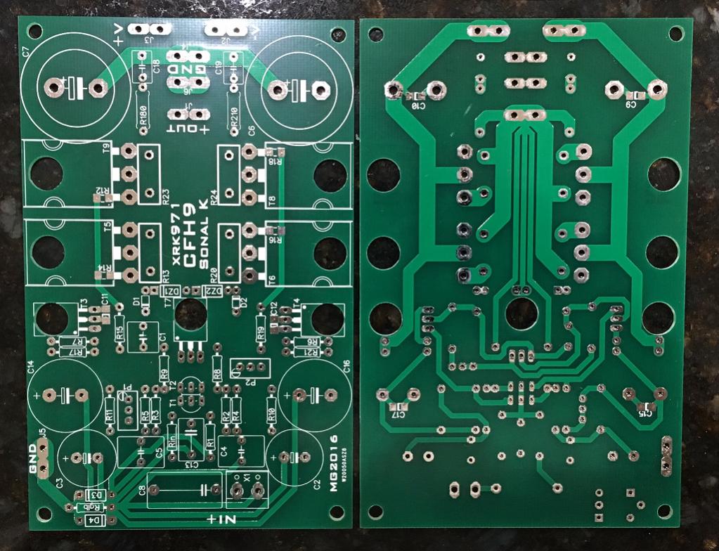
CFH9 GB PCB's are here
Just arrived in mail. They look good.
Made using Gerbers from here:
http://www.diyaudio.com/forums/solid-state/294834-cfh7-amp-40.html#post4876223
Schematic:
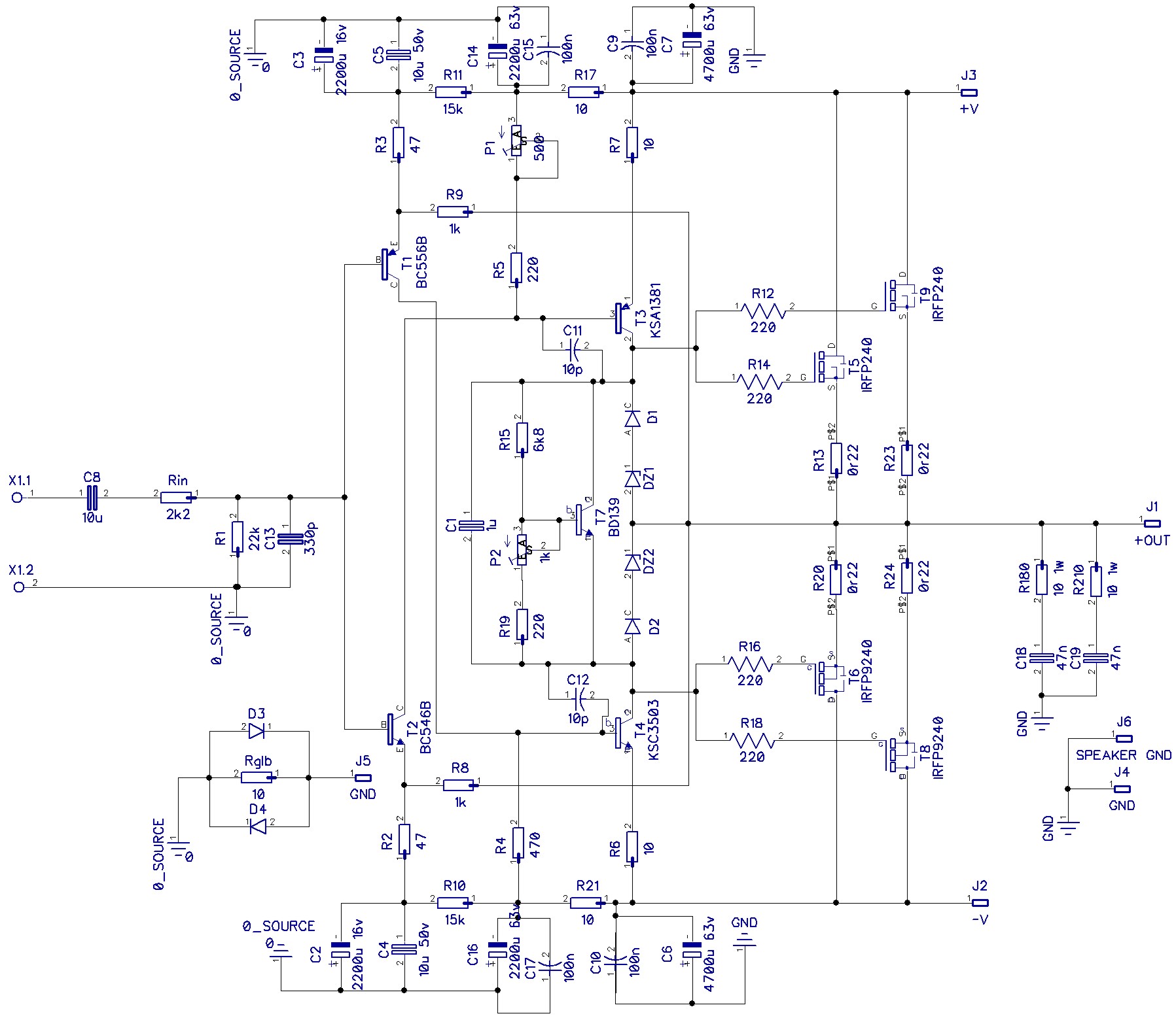
Parts placement:

I don't have a BOM yet but imagine it's very similar to the one I posted earlier with exception for SMT parts for 220R gate stoppers and 100nF bypass caps. I am not sure if the part designations are the same though so you will have to look at the schematic above to figure out.
Just arrived in mail. They look good.
Made using Gerbers from here:
http://www.diyaudio.com/forums/solid-state/294834-cfh7-amp-40.html#post4876223
Schematic:
Parts placement:
I don't have a BOM yet but imagine it's very similar to the one I posted earlier with exception for SMT parts for 220R gate stoppers and 100nF bypass caps. I am not sure if the part designations are the same though so you will have to look at the schematic above to figure out.
Attachments

Last edited:
xrk, very nice but you have D1 and D2 upside down on your schematic and the PCB. There is no overvoltage protection if connected like this.
Hi Sonal,is the(Sprint) CFH9 ver 1.02 a tested pcb?Thanks Marc, I totally missed those errors.
Reposting corrected gerber files of CFH7.
Those who downloaded sprint lay file rotate 4700uF capacitor on CFH7 ver1.07, CFH9 ver1.01, CFH9 ver1.02 layout. Move +ve and -ve sign to correct tab.
xrk, very nice but you have D1 and D2 upside down on your schematic and the PCB. There is no overvoltage protection if connected like this.
Hi dadod,
The mistake comme from me...Appologise. Chance, just reversing the two 1N4148 is enough to correct the issue so it's just the top silk that is wrong in this area. I join corrected schematic, layout and the bom for CFH9
Attachments


Last edited:
Schematic is still wrong.Hi dadod,
The mistake comme from me...Appologise. Chance, just reversing the two 1N4148 is enough to correct the issue so it's just the top silk that is wrong in this area. I join corrected schematic, layout and the bom for CFH9
CFH9 amp built
Not tested yet. Still need to mount on heatsink. Thanks for catching the diodes Dadod.
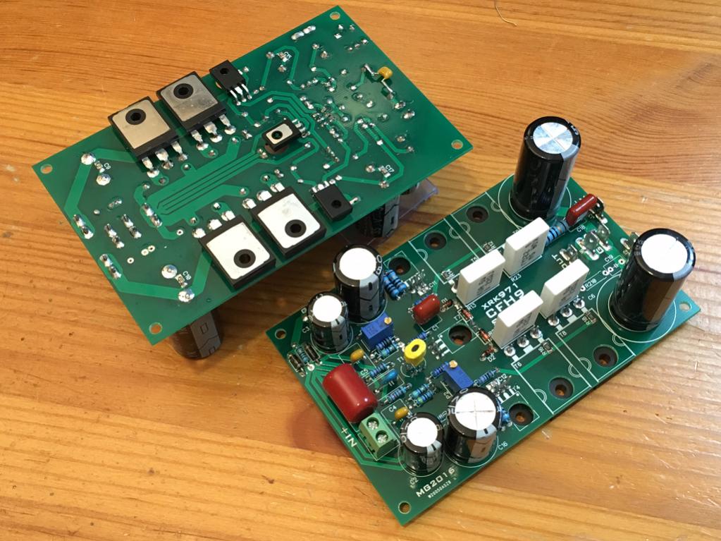
It will look something like this mounted on heatsink (with small fan):

Not tested yet. Still need to mount on heatsink. Thanks for catching the diodes Dadod.
It will look something like this mounted on heatsink (with small fan):
Attachments


Last edited:
Just arrived in mail. They look good.
The collector of T3 is dangerously close to its base.
Brian
T3 uses standard pin spacing for TO126. There are two pads for the small SMT 10pF cap. I don't see any issue as I have used many amps with TO126 packages and same pad spacing.
Just realized I can't mount two amps on one heatsink due to temperature compensation crosstalk.
Just realized I can't mount two amps on one heatsink due to temperature compensation crosstalk.
That should have read "the collector of T3 is dangerously close to the TRACK to its base.
Ok - I see what you mean on the underside. I will double check with continuity meter to ensure it's not shorted.
Hi Sonal,is the(Sprint) CFH9 ver 1.02 a tested pcb?
Hi Thimios,
My CFH9 Ver 1.02 and Idefixes CFH9 layout are almost identical, he used different grounding technique in his layout.
XRK is testing CFH9 pcb.

Regards,
Sonal Kunal
Will C15 and C17 (behind the 10R) see the full rail voltage? I am using 2200uF 35v caps there for now (don't have 2200uF 50v or even 63v caps) and am wondering if I can go above 35V.
Edit: never mind, just ran a sim and that cap pretty much sees full rail voltage.
One other thing I checked in the sim is the value of R9 on the Vbe multiplier. My sim shows 470R is better as it allows the pot to stay close to the middle of its range whereas 220R requires the pot to be closer to 93% full setting. This is to get a desired 140mA bias current.
Last edited:
Hi Thimios,
My CFH9 Ver 1.02 and Idefixes CFH9 layout are almost identical, he used different grounding technique in his layout.
XRK is testing CFH9 pcb.
Regards,
Sonal Kunal
Yes perfectly right ...that 's why your name is on...
Here are corrected files with Vbe resitor change 220 to 470....
Attachments


Last edited:
CFH9 Amp Tested: a Success
The amp was built per the new schematic with R19=470R and D1 and D2 reversed in direction relative to the silk screen. I did not have time to drill and tap 7 holes so used an existing hole to clamp the Vbe multiplier, the rest of the transistors were held down with tape pressure (they are quite flat as they were soldered in place from top while sitting on flat surface at proper height). Anyhow, connected to 35v rails with 10R safety resistors. Fired right up and bias is fully adjustable and is rock stable. I am running 150mA through each output device (or 300mA total bias current). DC offset is also easily adjustable and rock stable (I am using Hfe matched BC546/556's). Listened to a few tracks, sounds very nice. Will give detailed listening impressions after I get two amps in stereo.
For now, Sonal's & Idefix's layout PCB's are confirmed to be good and I will send out boards in a few days when I get to the post office.
Attachments

Last edited:
- Home
- Amplifiers
- Solid State
- CFH7 Amp