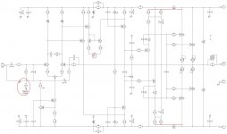
Some observations.
A (little) part of the output is on R3 via the feedback.I don't like that.
C14 and C17 are charged by the bootstrap since decharge is prevented by D9 and D10.There voltages will go up with the output level.
And other little things
Mona
A (little) part of the output is on R3 via the feedback.I don't like that.
C14 and C17 are charged by the bootstrap since decharge is prevented by D9 and D10.There voltages will go up with the output level.
And other little things
Mona
Attachments
Are your designs all becoming 2 sided layouts now?
Hi Terry,
I did my best to keep the board compatible with my original VHex+ boards in terms of size and holes placement. Also, I'm not good enough in layouts development - single layer requires more talent (and/or more time), than double-layer
However, I think - single layer is possible, if the form factor will be close to the square one. For example - it's possible to take your or Albert's square-kind-of VHex layout and update it accordingly (probably making it a little bigger).
Wanna give it a go? An great exercise, plus many diyers will appreciate the effort
Some observations.
A (little) part of the output is on R3 via the feedback.I don't like that.
C14 and C17 are charged by the bootstrap since decharge is prevented by D9 and D10.There voltages will go up with the output level.
And other little things
Mona
Mona, thank you for the comments.
I like the point with regards to the diodes and - connecting the bootstrap circuits your way make a lot of sense.
R3 - normal lifted ground. The feedback is high-impedance enough, so 10 ohm does not really hurt. Anyway - in case somebody does not like the lifted ground - R3 can be shorted.
Connecting R17 and R22 to the ground is not a good idea for a number of reasons:
- I'd like the power consumption of 15V parts of the front-end being the same;
- CE voltages and power dissipations of Q5 and Q8 must be the same for the best result.
Cheers,
Valery
Did you fit the bypass cap to the drivers' collectors?
Good one. I didn't try it like this - will play with it in the sim and see.
In this topology, the drivers' bases are rather close to each other, so their BC voltages will appear rather low...
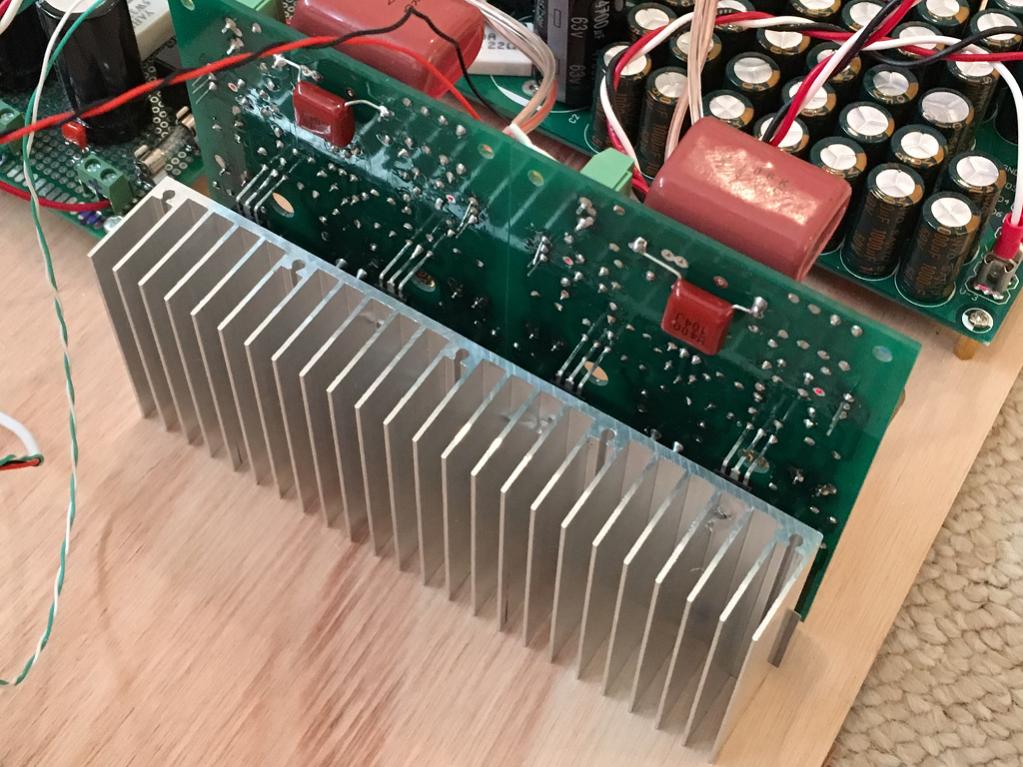
Thats's the problem isn't it? How to utilise the Power Dissipation ratings of these monster fets without resort to water cooling or other exotic methods. Matching parallel fets is difficult and I'd like to be able to use a single pair to build a high power amp but I'm not convinced these switching fets are up to the task.
Right, Christian - this is the biggest concern for this design. However, I believe, up to some 300W of output power is workable with high-performance heatsink.
The other concern was these monster-FETs huge input capacitance, but I seem to find a good way of driving them.
Jeff's test shows good performance. Now we need to see if it will really handle some power. If it will drive some 250-300W at the output (8 ohm) with this single pair - I'm happy
I had it running fairly loud on a 8R speaker for a half hour with a +/-70V supply. The C Channel scrap I had it mounted on wasn't really warm. I wouldn't use it for dummy load testing, but playing music really didn't generate much heat.
I'm going to test this on +/-84V supplies at 8 ohms, but eventually these will be driving a 4 ohm subwoofer with intended output to be 300W.
I'm going to test this on +/-84V supplies at 8 ohms, but eventually these will be driving a 4 ohm subwoofer with intended output to be 300W.
Terry, two layer pcbs are a pretty much a necessity for surface mount
In fact, for a single-layer, I would switch to TH parts completely.
I had it running fairly loud on a 8R speaker for a half hour with a +/-70V supply. The C Channel scrap I had it mounted on wasn't really warm. I wouldn't use it for dummy load testing, but playing music really didn't generate much heat.
I'm going to test this on +/-84V supplies at 8 ohms, but eventually these will be driving a 4 ohm subwoofer with intended output to be 300W.
Well, for 4 ohm load we can have an option with lower rails - just for keeping it more energy-efficient
I've got a pair of 45VAC transformers waiting for this project already. I need to figure out how to calculate heat sink for this yet. I normally use D Self's calculations, but the voltage loss through the mosfet output stage don't really work with his formulas.
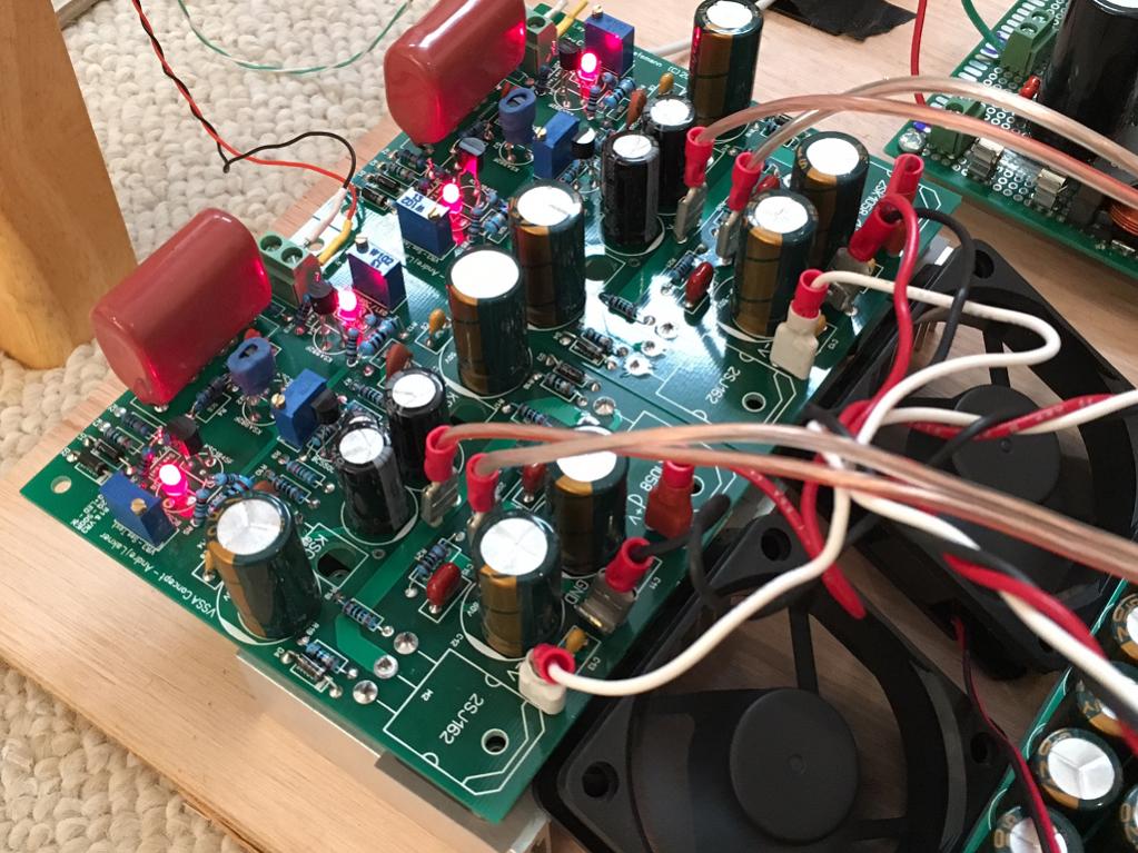
You might want to try simple fan attached to a much smaller heatsink - like a CPU cooler. They can achieve some dense cooling. The noise of fans bothered me but I find adding a 100R 2w resistor in series with 12v fan allowed it to still work well with regards to hear removal but be inaudible. Here is an example of two VSSA boards being cooked by single tiny heatsink and pair of fans. Heatsink barely gets warm. A larger sink and larger fans might work very well for your case. In the end costs less as huge heatsinks are expensive big and heavy.
I have it blowing through edges here but also works well with screwed directly to sink face.
But if we take anything from the PC industry - that is use of heat pipes and fans for best heat transfer. Heat pipes are the highest heat flux devices available - when properly designed can have up to the same flux (per cross sectional area) as heat from surface of the sun (!).
6 Double ended heat pipes and dual fans. This looks like it could fit directly to one IXIS.
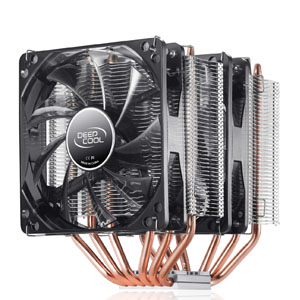
https://www.amazon.com/gp/aw/d/B00S0Q1XL6/
Last edited:
I've got a pair of 45VAC transformers waiting for this project already. I need to figure out how to calculate heat sink for this yet. I normally use D Self's calculations, but the voltage loss through the mosfet output stage don't really work with his formulas.
My gut feeling is that with those supplies you'll make about 200W /8R with this design, maybe a little less. The formula I use is:
Pd(max) = (Vdd*Vdd) / (2 * pi * pi * Rload)
So about 84W. I'd be looking for at least a 0.3C/W heatsink per channel and even that is going to run HOT at 40% full output.
Actually the biggest problem will be getting the heat from the transistor to the heatsink. I would start by slicing some Mica washers super-thin and coating both sides with artic silver paste or similar. It may even be necessary to mount the transistors to directly to copper blocks and then clamp these to the aluminum heatsink using kapton tape and grease for isolation.
Have fun!
Thanks. That's about what I came up with for a rough estimation, so my math likely worked.
I haven't been running this overly hard yet, but I'm not seeing any thermal issues so far. The devices themselves are running close to the heatsink temperature. This will obviously become more apparent as power increases though.
It looks like 10" of Heatsink USA's 10.080 profile should work nicely as a plate amp.
10.080" Wide Extruded Aluminum Heatsink - HeatsinkUSA
10.080" Wide Extruded Aluminum Heatsink - HeatsinkUSA
Fans help immensely with cooling, but are noisy. I plan to mount these in the back of a pair of subwoofers that are going into my home theater system, so fans are out.
That was my point - add a resistor between 12vdc and fan to lower speed until inaudible. It's amazing how much cooling is still left at this point. I can't hear my fans.
very nice looking set up.
TrueQuiet 120 - antec.com
running at reduced voltage these are truly silent.
Still better if you can do it without fans.
TrueQuiet 120 - antec.com
running at reduced voltage these are truly silent.
Still better if you can do it without fans.
very nice looking set up.
TrueQuiet 120 - antec.com
running at reduced voltage these are truly silent.
Still better if you can do it without fans.
Actually those are the fans in my PC in my living room right now. Add a little cat hair, and they become noisy too. Once they've run out of balance for a short time, cleaning doesn't make them quiet. If liquid cooling was more reliable I would go that route. For now, I've just banished fans from where I sit and run extender baluns.
You'll get better cooling with a copper shim - a piece of copper sheet/plate between the transistor(s) and the aluminium heatsink. The copper works as a heat spreader/pipe - very useful if your aluminium heatsink is much larger than your transistor, which is nearly always the case.
Some observations.
A (little) part of the output is on R3 via the feedback.I don't like that.
C14 and C17 are charged by the bootstrap since decharge is prevented by D9 and D10.There voltages will go up with the output level.
And other little things
Mona
I have checked the situation with C14 and C17 - their potential is not dependent on the output swing. At high swing (clipping) there is subtle modulation of the voltage at C14, C17 - some 25mVp, not an issue.
The current through R32 || R35 and R34 || R37 changes direction, but has the same positive and negative value, keeping potential at the rail unchanged.
- Home
- Amplifiers
- Solid State
- Sons of VHex