
MOSFET Circlophone #1 is ALIVE. It fired right up no issues
I am getting 180mA quiescent bias current through the 0.56R resistor. Singing now - sounds fine. Running on 35v rails at present.
Nice work Xrk. What transformer's VA you are using for the CP and total capacitance? I had 15,000uF per rail but I think at least some 22,000uF could be used (for my boards). I got 250mA, BJT's were not HOT, just need a bigger heatsink. Sound is very good though, very detailed.
I am using a 250va transformer with 35v rails on dual PSU's each with 4700uF x 3 per rail in a CRCLC config. With R of 5R and 0.56mH L.
I also have 300va transformer that gives 44v rails I can try next. Bias current is measuring 220mA across the 1R resistor. Heatsinks are warm but that's because they are kind of undersized. Not too hot though.
I am running into a problem with unit #2 - there is almost no bias current. So in debug mode now checking component values and solder joints etc. they were built simultaneously though in parallel so odd how one would have been different. Probably a bad transistor somewhere?
Last edited:
Nice to see you have your MOSFET Circlophone up and running!
The DC-offset is on the high side, best choice is to match the J-FETs.
Otherwise you could try to adjust the offset with a trimpot. Connection between R26/R37 and R28.
I have some nice LInear Systems SK389 single can single die matched input JFETs - that should solve the DC offset issue but the legs will need to be creatively crossed as pin outs are different (why?).
I have some nice LInear Systems SK389 single can single die matched input JFETs - that should solve the DC offset issue but the legs will need to be creatively crossed as pin outs are different (why?).
The nice SK389's could be tested in the Inverted J-FET CP. Pls, have a look first in what Elvee said regard it:
http://www.diyaudio.com/forums/solid-state/189599-my-little-cheap-circlophone-146.html#post4441631
And yes, I remember now your PSU images
")
Hope that Jacques Antoine and other members will join it here, soon...
The nice SK389's could be tested in the Inverted J-FET CP. Pls, have a look first in what Elvee said regard it:
http://www.diyaudio.com/forums/solid-state/189599-my-little-cheap-circlophone-146.html#post4441631
And yes, I remember now your PSU images
Hope that Jacques Antoine and other members will join it here, soon...
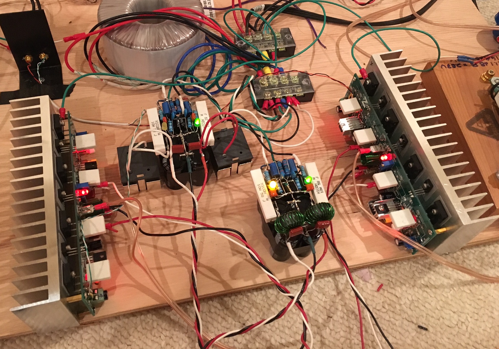
I'm actually using two of these P2P units with qnty 6 x 4700uF ea.
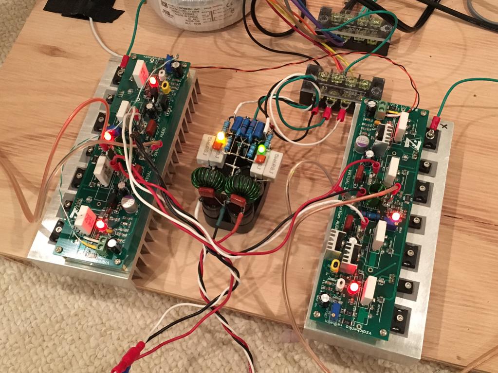
Here is one powering two Vhex's. When I switched to dual PSU's the soundstage opened up like you can't imagine. It's like wow. One of the cheapest upgrades to your sound is to use dual PSU's.
Here is two of them (second one is using split core Coilcrafts):
So regarding the LSK389, Elvee says it would still have a big offset? I guess I may be better of with a trim pot. I am at 80mV now so with 27dB gain it means my offset is only 3.6mV at the LTP?
Btw, are there any others who have tried Piersma's circuit with the hexFET outputs?
Last edited:
FiFo Circlophone
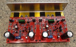
To differentiate the version I built (which I hear, there are 3 other builds), I will call it the FiFo C-phone.
FET-in-FET-out Circlophone.
The sound of the FiFO C-phone amp is very nice - I detect a slight warmth, maybe a harmonic structure a bit different than say my FH9 or the JK VSSA. Very dynamic though, and clear. I will await a stereo set before further careful listening impressions.
Piersma says that an option exists for balanced input, hence two input caps - but ground the negative input for unbalanced operation as first cut to test functionality prior. There are some resistor value changes that will be coming to make the balanced version work though.
I like how colorful all the parts are on your board - nice work. Are you using a macro lens or just a close focusing cellphone cam? Photos are great - like you have a macro ring light.
Is there a schematic for the balanced version? I have balanced mos fet amps, but 50W Class A burns a lot of power. I have only just caught onto the circlophone design and sliding Class A would save a lot of power!
Provisions for a balanced operation were made on the PCB but the balanced version is not (thoroughly) tested. Schematic will be only be released once the testing is done and the proper operation of it is approved. So not available at this moment.
Thanks, I'm looking forward to it.
I'm having some real problems getting the second channel of my FiFo Circlophone to work. Will probably need group eyes in the problem to solve as I have pretty much exhausted all my own debugging techniques short of removing every component and testing and reinstalling.
The problem is that the main output FETs are not really turned on or flowing any bias current. I am getting total current into amp of 28mA (0.28v through 10R safety resistor). So something in small signal and VAS or Driver stage is not working.
Sound will come out only if volume turned up high and it is really distorted like it has a huge crossover distortion switching on and off to inaudible.
What I have done is verified all resistors are correct. Looked for visual cold solder joints or solder bridges. Replaced all transistors except drivers and output hexFETs. The 2sc4793 drivers were removed and tested fine with an Hfe tester. The output hexFETs appear to still be good (not shorted into low impedance).
So what to do next? Customarily at this point, I remove the output hexFETs and monitor the gate voltage to see what it is doing. Then I remove the drivers and monitor their base voltage. Then I keep going upstream until I find the culprit. However, the Circlophone topology is beyond me so I have no idea what to do next or which branch to go. But like I said, all 14 transistors upstream of the outputs and their drivers have been replaced including the input JFETs.
I can provide detailed photos of that helps. What is hard is I can't make sense of the schematic and the actual part numbers on the PCB. There is not a schematic that has 1-1 correlation.
Thanks in advance.
A few more clues: this board is very fragile and I managed to lift off a couple of solder pads and it's attached trace. I tried to fix that by verifying conductivity but maybe there is an issue here? It's at the small signal Schottky barrier diode. I measure a 0.1v drop across this diode and it seems to be conducting to its upstream points and downstream points. Would a failure of the Schottky signal diode here cause the symptoms I am seeing? I am not using the specified Schottky BAT14 part but some other generic 1N893x or other (can't remember off top of my head). It works fine on first amp though.
Last edited:
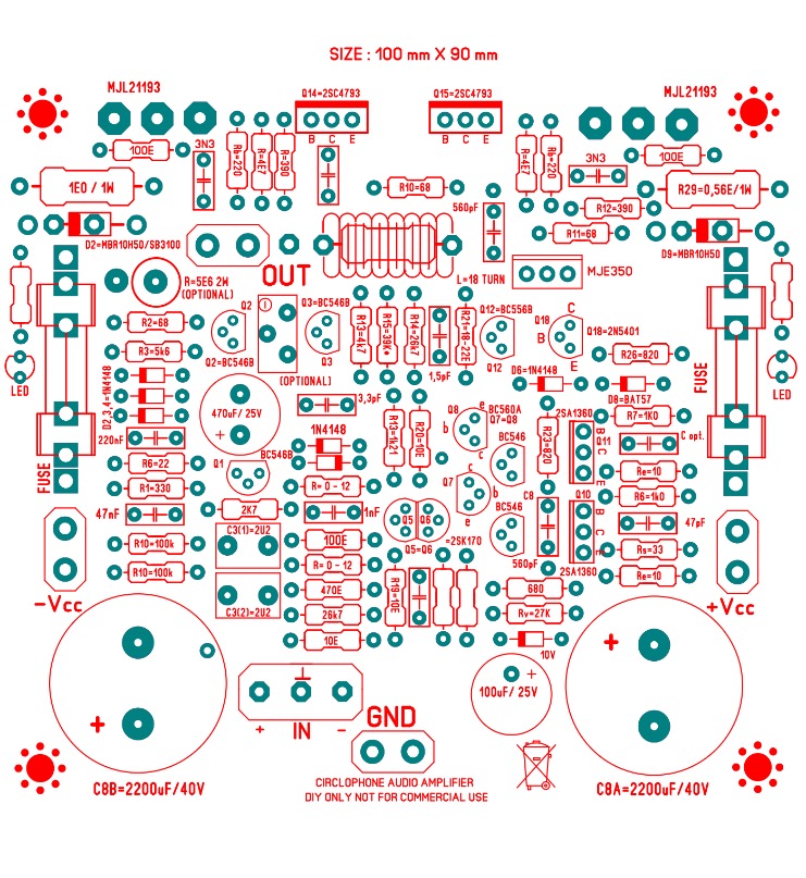
MOSFET OPS
XRK,
here's the schematic: http://www.diyaudio.com/forums/solid-state/189599-my-little-cheap-circlophone-122.html#post3769882
Disregard the front-end in the schematic only take a look at the output stage.
XRK,
here's the schematic: http://www.diyaudio.com/forums/solid-state/189599-my-little-cheap-circlophone-122.html#post3769882
Disregard the front-end in the schematic only take a look at the output stage.
Last edited:
- Status
- This old topic is closed. If you want to reopen this topic, contact a moderator using the "Report Post" button.
- Home
- Amplifiers
- Solid State
- Inverted J-FET Circlophone Builders thread