Cdom
OK, here we go.
Simulated with +/-40V rails.
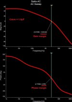
As expected, with Cdom = 1.8pF the amp is practically unstable. The fact that it works at full rails is just a matter of certain luck. With lowered rails, at some point, the circuit becomes dc-unbalanced and at the same time converts to "screaming oscillator".
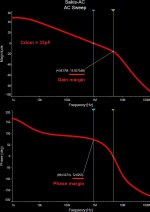
With Cdom = 33pF it's a completely different story. Not the best in class, but it's unconditionally stable. Regardless of the rails voltage.
In this configuration, it shows THD1 = 0.07%; THD20 = 0.1% (50W @ 8 ohm load) and good enough step response (no overshoot).
OK, here we go.
Simulated with +/-40V rails.
As expected, with Cdom = 1.8pF the amp is practically unstable. The fact that it works at full rails is just a matter of certain luck. With lowered rails, at some point, the circuit becomes dc-unbalanced and at the same time converts to "screaming oscillator".
With Cdom = 33pF it's a completely different story. Not the best in class, but it's unconditionally stable. Regardless of the rails voltage.
In this configuration, it shows THD1 = 0.07%; THD20 = 0.1% (50W @ 8 ohm load) and good enough step response (no overshoot).
Attachments
My estimation was 47PF
The tests i have made Do not seem to effect performance of amplifier and remains stable for 2days now
Yes, with 47pF you get pretty close results.
If you go up to 100pF - you affect open loop bandwidth and THD20 grows.
Down to 22pF - stability margins become too low.
33pF...47pF is a good working range for this design.

The LTP current is actualy balanced because the VAS degeneration is so high that it raise the base voltage at the convenient value, but that s a poor design anyway, the lowish Cdom is of no effect, it should be raised by 10x, as it is currently there should be a huge peak at about 5MHz in the frequency response, and of course a consequent lack of stability.
With a few bills you can get people saying very nice things about one s product, what is sure is that those magazines have no regard for their readers money.
Wahab, absolutely right. Simulation shows a huge peak at 2.837MHz with the loop closed (Cdom = 1.8pF) - pretty much in line with your estimation

Wahab, absolutely right. Simulation shows a huge peak at 2.837MHz with the loop closed (Cdom = 1.8pF) - pretty much in line with your estimation
Since i have typical schematics in my library i made a rapid sim using a C5200/A1943 + A1837/C4793 OS.
Illimzn was right that the VBEM cap is not connected as it should be and this increase instablity wth the basic schematic as i get oscillations unless i connect the cap in the VBEM EC junctions, in this latter case it s only marginaly stable if Cdom is not substancialy increased, the gain and phase margins at 33pF are of course the one you computed.
Since i have typical schematics in my library i made a rapid sim using a C5200/A1943 + A1837/C4793 OS.
Illimzn was right that the VBEM cap is not connected as it should be and this increase instablity wth the basic schematic as i get oscillations unless i connect the cap in the VBEM EC junctions
Yes, this is because as it is drawn, for AC the VBEM is effectively a current source in parallel with the C-B resistors. It will do temperature compensation but not as a voltage source (which is what it is supposed to be). If any instability happens, because the top and bottom half of the output stage are inherently different in ways that matter for this condition, there will be huge cross-conduction and the output stage will destruct. What is more, as it is the bias current starts off at the highest ('infinite') value at the startup of the VAS CCS which also has to charge that capacitor initially to Vbe. Normally this condition is fairly short when the amp powers up to full rail voltages. But should the rails be insufficient, it might latch up in a cross conduction state. Very much a recipe for disaster even with Cdom fixed.
Yes, this is because as it is drawn, for AC the VBEM is effectively a current source in parallel with the C-B resistors. It will do temperature compensation but not as a voltage source (which is what it is supposed to be). If any instability happens, because the top and bottom half of the output stage are inherently different in ways that matter for this condition, there will be huge cross-conduction and the output stage will destruct. What is more, as it is the bias current starts off at the highest ('infinite') value at the startup of the VAS CCS which also has to charge that capacitor initially to Vbe. Normally this condition is fairly short when the amp powers up to full rail voltages. But should the rails be insufficient, it might latch up in a cross conduction state. Very much a recipe for disaster even with Cdom fixed.
Fingers crossed that C206 a 4.7uF actual value is not critical tolerance wise - this being an electrolytic possibly at the high end of the range.
If there is nothing in that, a string of diodes/zener between Q206 collector and emitter to clamp the bias voltage between the driver transistors to a safe level during power up?
Easier to just re-solder it to C-E. The VBEM then works as expected, the 4u7 bypasses it for HF (such as it is) and also it initially starts at 0V initial charge = minimum bias current. Fixes 3 issues with moving one leg of the cap to a different place.
I agree.
Easier to just re-solder it to C-E. The VBEM then works as expected, the 4u7 bypasses it for HF (such as it is) and also it initially starts at 0V initial charge = minimum bias current. Fixes 3 issues with moving one leg of the cap to a different place.
I think you might be forgetting the role of C207 and disabling the turn on delay RC connected to Q206 base. Were you thinking in terms of C-B using Miller effect to allow the use of a smaller close tolerance plastic capacitor.
Last edited:
- Status
- This old topic is closed. If you want to reopen this topic, contact a moderator using the "Report Post" button.
- Home
- Amplifiers
- Solid State
- Attention please oscillation