Mods to an amazing Adcom GFA-555 amplifier.
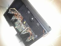
The transformer has been covered in athletic tape and has a slightly larger than semicircular piece of TI-shield to orient the magnetic field away from the system. This piece of TI-shield was filed on edges to reduce outwards transmission and enhance internal reflected dissapation as well as absorbtion by the transformer. The shield also functions to isolate the transformer from the capacitors to be located behind it. TI-Shield was baked at 600 in oven and slowly cooled to form a porous oxide layer to enhance absorbtion, surface dissapation, and reduce emission of both trapped and surface signals.
The lower bin will be filled with Urethane gel Shore-40. Other capacitor circuits will be in and outside the bin as well.
The transistors and gain/control board will be located in the upper bin which is to be filled with shore-40 urethane gel as well.
Other capacitors to be used are 6 groupings of Solen capacitors as well as 4 ASC capacitors.
Research to be done on speaker binding posts and RCA bindings and fuse holder, goal intended to keep costs low. Most likely will use original equipment included with Adcom GFA-555 save IEC recepticle where a fururtech is to be used.
Nah, a ~kiloliter cinder block subwoofer with 12" woofer will tax even this setup pretty severely.
Should power a pair of the big paradigm entry level floorstanding speakers quite well with the polypropylene larger woofers swapped for the paradigm mini monitor metal coned woofer.
Should power a pair of the big paradigm entry level floorstanding speakers quite well with the polypropylene larger woofers swapped for the paradigm mini monitor metal coned woofer.
Project has been modified to use original chassis with the 8 stacked Nichicon capacitors and shore-40 urethane gel. A NTC thermistor will be implemented along with a knife switch or deft plug switching to deal with the significant in rush current.
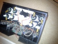
The center tap on the primary has two polystyrene film caps wrapped around the insulator along with two quarter watt 1k resistors. A cardas golden cross power cord has been attached to the chassis directly. Capacitors affixed using double sided automotive tape. Above shown rectifier bridges used.
The original project will be spurred to a new solid state design using a modified dynahi topology using higher current devices or the bins of Hfe tested transistors I have sitting around. Decision to follow circulatron 300b tube project.
Photos of adcom to come.
Last edited:
I have added 4 polystyrene capacitors to the top of the Nichicon capacitors. Additionaly I have added a polystyrene capacitor to the top of the toroid placed underneath the input board. This polystyrene has two 5Kohm quarter watt metal film resistors taped non conductivly to the polystyrene capacitor.
Look closely at the attached photo for the polystyrene capacitors are quite close to level. The photo shows them as quite skewed in direction as well as horozonttality.
Look closely at the attached photo for the polystyrene capacitors are quite close to level. The photo shows them as quite skewed in direction as well as horozonttality.
Attachments
Last edited:
- Status
- Not open for further replies.
- Home
- Amplifiers
- Solid State
- Adcom GFA-555 mods