Hello all,
I am in the process of (slowly) restoring a Pioneer SX-1250 receiver. My understanding is that two of the transistors- part number 512-KSA992FBU, NPN 120V 0.5A 120 MHz need to be gain matched. I only purchased enough for the restoration and know that I may need to buy many more, but my questions have to do with the gain matching process. I bought a cheap (ETEKCITY) DVM with hFE.
So, my questions are:
1. Is a cheap DVM acceptable for this testing or should I build a circuit for the testing that may be more accurate?
2.What should the range be for matching with these transistors as a percentage? I intend to keep the receiver and have 56 year old ears.
3. Where is the hFE range listed on the data sheets for transistors?
This is my first restoration and a new hobby for me. I have a much better DVM but without hFE capacity. I hope to have this as a long term hobby.
I appreciate your patience with this newby's question.
Dave
Hi Dave,
Your ears are younger than mine young feller! And I can hear just fine and enjoy equipment running at it's best. So age doesn't really have a lot to do with anything.
You need to match transistors in diff pairs as closely as you can. Your Hfe test in the meter, if used with care, only provides a pre-selection for the real matching process. The match is critical to distortion levels. The bad news is that beta is very temperature sensitive. The good news is that this characteristic forces you to do things properly.
So how to make the temperature term drop out of the list of variables? It's done the same way that amplifier designers use the diff pair. Create a long tailed pair using a current source. Stick your pre-selected transistors into sockets while they are touching and shield them from ambient air flow. I find s foam cover works well, then use a small box to block air currents. You can run the pair at the target tail current, or even differing currents. Higher currents will settle before lower currents will. So a 6 mA tail will settle faster than a 1 mA tail current. It'll be more stable too.
What to measure? Well, again you're in luck. You measure the difference between the two collectors - a null measurement. AS long as your cheap meter indicates zero with a short across it's terminals, you're good to go. Record the transistor matches and their differences. No matter how you do this, some time is required to allow thermal equilibrium between the transistors to be achieved.
Install your matched pairs similarly to how you test them. I use some thermal compound between the parts, then heat shrink the two together. Works like a charm.
So what is the benefit? More stable DC offset, and lower DC offset. A perfect match will generate the amount of DC offset that is designed into the amplifier. So that's good, but not good enough for the amount of labour involved. The other huge plus is the lowest distortion that circuit is capable of (as long as the outputs are also matched). The diff pair is where the output is subtracted from the input to generate an error signal. So a perfect match will send a more perfect error signal down the line which translates into low distortion. If they are not matched, the subtraction is flawed and you do not receive the distortion performance you paid for in the first place.
The more transistors you buy to test, the greater your percentage yield will be. So it pays to buy many. Often the same transistors can be used as substitutes for many others, so your personal hoard of matched parts will be used. Try to select low noise, high gain examples. Some at 50 or 60 volts and some at 120 volts NPN and PNP will cover your bases pretty well. I've done this for years, and it really works well.
-Chris
You may read Leach documentation ...
The Leach Amp - Part 2
you will find usefull information ... if you have enough time read the other pages linked to this one ..
The Leach Amp - Part 2
you will find usefull information ... if you have enough time read the other pages linked to this one ..
You're missing the one problem that prevents all the other common attempts at getting good matches.
Temperature variation!
If you can't control this, you can't match a darned thing. Sorry, but this is true.
Experiment: Stick a transistor in your favorite beta measuring device. Let it settle and note the reading. Now blow on it - what happens? Try pinching it between your (normally warm) fingers. What happens?
So you're going to get good numbers trying to match parts this way? I really don't think so.
-Chris
There is such a circuit for selection of transistors for h21e and check UceR.
It is clear from all electrical circuits.
It is clear from all electrical circuits.
Attachments
Last edited:
Hi T117,
These instruments still do not regulate or balance the temperature of the unit under test. The actual goal is to match, or balance, a pair of transistors. When the semiconductor manufacturer generates curves for transistors at Tc=25°C, they control the case temperature to 25°C. When they say ambient temperature is 25°C, they allow the parts to settle into the controlled temperature, then run the tests. Since this is unreasonable for the average person, I designed a jig that balances two transistors as a pair causing the temperature term to be common to both and therefore drop out.
If you can't either control the junction temperature, or cause it to become unimportant, you can not match transistors. I'm very sorry, but this is the truth.
To prove my point, serious matching of transistors generally requires matching on the wafer and co-mounting the die in a single package. Or, as in the case of the LM394 (I thinkthe # is right), the two die are probed in the wafer and are installed as one piece into a package. The LM394 takes this further and is actually made up from many small transistors in parallel and mounted in a single unit onto the package. If you can't do that, then the best you can do is balance the two devices against each other, then tie their cases together to test them for a match. Once matched, you fasten the two parts together, then make the ambient the same for them (heat shrink tubing). You could add a shroud or cap as long as they were not running too warm.
Why match the temperature? Because semiconductors are extremely sensitive to temperatures. So if you can't control the temperature, or balance two devices in the same thermal environment, you can not match them effectively.
Once the circuit and PCB are finalized, this device will be available in the DIYAudio store. I feel it will really help our members to be able to obtain extremely tight matching. I routinely match transistors so close that I have to also match the degeneration resistors to prevent throwing the match out. They can be extremely tight. Measured and listening performance is always improved by doing this if the amplifier has a good design.
-Chris
Hi T117,
These instruments still do not regulate or balance the temperature of the unit under test. The actual goal is to match, or balance, a pair of transistors. When the semiconductor manufacturer generates curves for transistors at Tc=25°C, they control the case temperature to 25°C. When they say ambient temperature is 25°C, they allow the parts to settle into the controlled temperature, then run the tests. Since this is unreasonable for the average person, I designed a jig that balances two transistors as a pair causing the temperature term to be common to both and therefore drop out.
If you can't either control the junction temperature, or cause it to become unimportant, you can not match transistors. I'm very sorry, but this is the truth.
To prove my point, serious matching of transistors generally requires matching on the wafer and co-mounting the die in a single package. Or, as in the case of the LM394 (I thinkthe # is right), the two die are probed in the wafer and are installed as one piece into a package. The LM394 takes this further and is actually made up from many small transistors in parallel and mounted in a single unit onto the package. If you can't do that, then the best you can do is balance the two devices against each other, then tie their cases together to test them for a match. Once matched, you fasten the two parts together, then make the ambient the same for them (heat shrink tubing). You could add a shroud or cap as long as they were not running too warm.
Why match the temperature? Because semiconductors are extremely sensitive to temperatures. So if you can't control the temperature, or balance two devices in the same thermal environment, you can not match them effectively.
Once the circuit and PCB are finalized, this device will be available in the DIYAudio store. I feel it will really help our members to be able to obtain extremely tight matching. I routinely match transistors so close that I have to also match the degeneration resistors to prevent throwing the match out. They can be extremely tight. Measured and listening performance is always improved by doing this if the amplifier has a good design.
-Chris
You're absolutely right. But. Selection for һ21е reduces INPUT OFFSET CURRENT, and we are interested in, in addition, the INPUT OFFSET VOLTAGE. To reduce this last to be measured and Ube, which often has a variation.
In fact, a high degree of matching of the transistors in the amplifiers is not as important. The servo helps to eliminate the effects of unbalance in the input stage.Remain to know what happens with distortion. About this I have no data.
Hi T117,
It's not the DC offset we are worried about. It is how effective the diff pair is in comparing the input with the signal output to cancel distortion. It doesn't take much unbalance to affect how the amplifier sounds (for some), and I can certainly measure the difference. Look at the residuals from a good THD meter with a spectrum analyzer and you will see. That's assuming the amplifier is of good enough quality so that it matters.
This is a very real effect. There are app notes and books that support this if experimentation isn't enough. Even a thought experiment should show this to be true. The diff pair is crucial to how the amplifier operates.
-Chris
Hi, Chris.Hi T117,
It's not the DC offset we are worried about. It is how effective the diff pair is in comparing the input with the signal output to cancel distortion. It doesn't take much unbalance to affect how the amplifier sounds (for some), and I can certainly measure the difference. Look at the residuals from a good THD meter with a spectrum analyzer and you will see. That's assuming the amplifier is of good enough quality so that it matters.
This is a very real effect. There are app notes and books that support this if experimentation isn't enough. Even a thought experiment should show this to be true. The diff pair is crucial to how the amplifier operates.
-Chris
Without the use of special monolithic pairs from the problems you described, to get rid of difficult. The THD of the cascade depends on the scope changes the current of the transistor. Therefore, a more easy way - by increasing the gain voltage of the other cascades to force the transistors of the input differential stage to work with the least possible change in the current. I do, based on this understanding, the results are still good.
The Fairchild datasheet (September 2015) page 2 shows hFE....................
3. Where is the hFE range listed on the data sheets for transistors?..............
hFE1 and hFE2 are there and there is an hFE2 note appended after the table.
hFE2 varies from 200 to 800 in five grades lettered P to E.
This letter should be on each device after the main type name.
Unfortunately the datasheet does not show their naming layout.
There is probably and italic F on the front, near top left.
Does it say KSA992 FA, or A992 FB, or something else?
Is there a date code appended?
Are there codes moulded into the back?
Last edited:
Andrew-
Thank you for your help. I only printed the first page of the Fairchild data sheet for B-C-E configuration help on installation, but found the Hfe info with your help. The transistors I have have the markings "A992" and "FCE 43" on the flat side and the letter "D" imprinted on the radius side.
So, I'll order a bunch more from Mouser, build the Hfe testing circuit and seperate them out by Hfe readings, then select the 4 transistors that are closest in readings for use on the 2 Power amp boards.
I welcome any other advice you can provide on this.
Thank you all again.
Regards,
Dave
group them into batches that have similar hFE using the transistor facility on a DMM.
Then select from a batch to insert REF & DUT to try to find matched pairs.
You need to check hFE (test1) AND see if they pass similar current (test2) when both are fed with the same base voltage
for test1 you select a base resistor value that allows you to measure the base current.
for test2 you need to select a base resistor value equal to zero ohms.
Andrew-
So I figured out how to test for Hfe on the cheap multimeter using the Hfe function and PNP slots. The transistors fall within the range specified by Fairchild on the data sheets which is 150 to 500, most of the ones I have tested are in the 410 to 429 area. The next step is what I now need help with. Please know that I appreciate you being able to put this as simply as possible. My nicer DMM has a "duty" setting and a "REL" setting but I see no "REF" function. Would I be better off making a simple test circuit for the next step?
Thank you all again,
Dave
Thank you for your help and patience/understanding.
Assemble a Long Tail Pair jig. It must have a pair of accurately matched collector resistors. It is better if you can have a stepped current value CCS for the tail.
It's what I and at least two others have recommended on this Forum.
I have found that I need two forms of the LTP jig.
ver 1 has base resistors fed from an adjustable voltage via a potentiometer. The voltage drop across the two base resistors allows one to measure the base current and from that determine the hFE when the REF device is clamped to the DUT device and both are operating at a known and equal Power dissipation (Pdiss).
ver 2 has no base resistors. The adjustable base voltage via the pot supplies directly to the two bases. There are no emitter resistors. This allows measuring the current passing through the two collector resistors and/or measure the Vdiff at the collectors.
The arrangement described above ensures that Vbe for both REF and DUT are the same. If you have the same Ic then you will also have the same Pdis and thus the same Tj.
Since you chose two almost identical hFE, you now have Ic, Ie, Ib, Pdiss, Tj all matching for the Vbe you set up.
If you now change the CCS tail current to allow different Ic and find that two Ic still match you have found a pair of devices that make a well matched LTP pair.
This is time consuming.
I use two 3socket 0.1" Single In Line (SIL sockets) glued together to form a 6socket jig for the two transistors. I clamp the flat faces together with a spring clamp, (a tiny elastic band would do the same, but I have never seen one small enough).
Last edited:
")
I see that this question has bee asked a few years before on another thread on this board. My plan is to build the circuits on the Elliot Sound Products page for further testing. We'll see how that goes! Good experience for me if nothing else.
I feel like I dove into the deep end of the swimming pool with this project when I should have started at the wading pool end. I have successfully recapped a few speakers, but nothing like this SX-1250. I may never catch up to many of you guys as far as understanding of electronics but hopefully I have fun trying.
Thank you again!
Kindest regards,
Dave
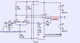
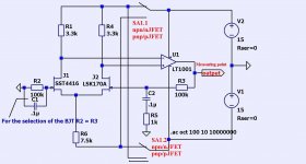
For semi-automatic selection of matched pairs of JFET and BJT.

The idea is that the OpAmp drove the J2 and balanced currents J1 and J2. In place of the J1 and J2 through connector placed a pair of JFET or BJT, and the output OpAmp to measure the voltage of the error and pick up a pair of JFET or BJT at the lower value.
For the selection of the BJT R2 = R3.
You can choose OpAmp any cheap device.
Attachments
Hi Andrew,
Building a diff pair using base resistors allows you to check the base voltages as well. You will find that devices with close beta will also match in Vbe.
Hi T117
A simple diff pair as described is ... simple. No op amps required. What I used were a pair of 100R 0.1% resistors for each NPN and PNP (or N-ch and P-ch). I use Nelson's (and others) method of finding Idss and Vpinch for J-Fets. I stick them in my jig more for interests sake, and use the closer matches based on all those tests.
No matter how you match transistors, temperature change is your sworn enemy. The same holds true for diff pairs in circuit. It pays to lay out your board so you can tie those transistors together and block air currents if at all possible. If you get close matches using a diff pair jig, you should also match the degeneration resistors if they exist.
What changes with matched transistors? Distortion drops (I have measured this change using an HP 339A distortion measuring set. I need something better now. How far the THD drops depends on how bad the mismatch was to begin with. The other change is a more stable DC offset. Some circuits have a designed in offset, so the output voltage will then agree with a calculated value of DC offset. Circuits designed for zero DC offset will often settle in less than 5 mV. Also, DC offset drift with temperature and warm up time is reduced or eliminated. In short, nothing but good things happen if you match your diff pair transistors carefully, then install them properly.
-Chris
- Status
- This old topic is closed. If you want to reopen this topic, contact a moderator using the "Report Post" button.
- Home
- Amplifiers
- Solid State
- Transistor gain matching