Well they are meant to be on or off in the intended application.
"It was an act of the purest optimism" to have supposed it might work in the first place.
as Mr. Wensleydale's unlucky customer once remarked.
Just for sh*ts and grins (Hee-Haw style - "I'm a sh*ttin' and I'm a grinnin'), I put together a folded cascode preamp circuit simulation using a pair of the J107s in parallel. Results were indifferent at best, and the parts are consummate current hogs unless you really load up on source degeneration or (gasp!) come up with some negative gate bias. Even biased at 18mA apiece, results (both gain and distortion) were less than spectacular. Add to that ringing endorsement, >100pF apiece in gate capacitance. I fear that the devices will sleep in their plastic bag until I figure out some use for them, if ever. I wonder what Horowitz and Hill were thinking? I have devices that are far less hoggish and capacitive that will work better.
Don't even talk to me about using the J105s in the linear region...
Don't even talk to me about using the J105s in the linear region...
Don't even talk to me about using the J105s in the linear region...
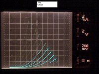
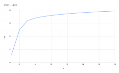
The plot below is a J105 with -6V added to the Gate steps. The DUT is an old Siliconix part that shows triode like curves. Not all J105's do this. The Fairchild parts I got from Mouser didn't. If you have parts that do this, I'll buy 'em.
This patent from the 70's calls the triode-like behavior prior art.
Download the pdf here: FIELD EFFECT SEMICONDUCTOR DEVICE HAVING AN UNSATURATED TRIODE VACUUM TUBE CHARACTERISTI - Zaidan, Hojin Hondotai Kenkyn Shinkokai
I think the triode-like curves are a process mistake or anomaly. I've only seen it on JFETs with low Rds intended to be used as switches. They are difficult to bias but noise is fairly low and input capacitance is high.
Attachments
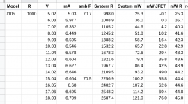
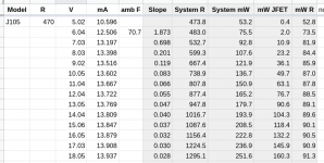
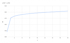
I have a small number of J105 from tayda and took some data on one.
My test circuit is the typical JFET constant current source, with a resistor in series with the source.
For each data point: a voltage from a lab supply was placed across the system (JFET + resistor), then approximately 1 minute later the voltage and current were measured.
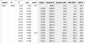
1k and 470R resistors were used.
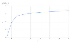
So, it looks like it does not make the best current source. It requires quite a lot of Vds before it flattens out, and isn't actually particularly flat in the flat region.
My test circuit is the typical JFET constant current source, with a resistor in series with the source.
For each data point: a voltage from a lab supply was placed across the system (JFET + resistor), then approximately 1 minute later the voltage and current were measured.
1k and 470R resistors were used.
So, it looks like it does not make the best current source. It requires quite a lot of Vds before it flattens out, and isn't actually particularly flat in the flat region.
Attachments
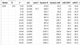
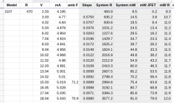
I added a "slope" column (difference in voltage from the previous measurement over difference in current from the previous measurement), and shaded the calculated columns in light grey.
Attachments
I cobbled together my J105 IDSS test jig today, and tried it out on a sacrificial device.
Mark, I like your idea of pulse testing. I believe my method is likely producing results which are distorted by the temperature coefficient of the JFET.
I do have a digital scope, but it only has 8-bit resolution, so varying the signal from 0 to full scale during each pulse is not going to give me the results I'm looking for.
Perhaps if I power the DUT continuously, but vary the voltage across a certain window at a reasonably high frequency? I.e. a power supply which can vary sinusoidally from 10V to 11V at 1kHz, for example. I could then use AC coupling on the scope at "zoom in" on the difference in current over this small window, to get a good picture of the current source's performance.
I suppose another approach would be to cobble together a microcontroller and a high-speed ADC chip.
Any other ideas are welcome!
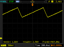
Cobbled together a few op amp cookbook circuits and came up with this to test constant current sources via an oscillating voltage window.
It should be a roughly 1kHz, roughly 1V magnitude saw wave with a DC offset adjustable in 12 steps. Powered by three 9V batteries, should be good for at least 20mA load.
I'll solder it up tomorrow and verify the circuit, then draft up a PCB.
It should be a roughly 1kHz, roughly 1V magnitude saw wave with a DC offset adjustable in 12 steps. Powered by three 9V batteries, should be good for at least 20mA load.
I'll solder it up tomorrow and verify the circuit, then draft up a PCB.
Attachments
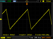
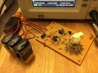
Got a prototype working.
Some slight changes to the circuit:
Now time to test it on some CCS JFET circuits!
Some slight changes to the circuit:
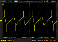
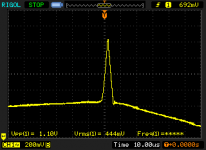
- Turns out pin 2 of the saw gen needs at least about 1.5V to start / sustain the oscillation. Replaced the voltage divider with an LED-based Vref (1.75V with my particular red LED).
- The saw gen creates spikes which didn't show up in simulation. I added a low-pass on the saw gen output.
Now time to test it on some CCS JFET circuits!
Attachments
I´m not 100% how you mean that but in LTspice for example you can add a random number to any of the transistors parameters.A typical SPICE model has no means to specify spread of parameters.
For example instead of BETA=20 you could say BETA=20+flat(5) to give values of 20+-5. In order to simulate a good spread you´ll have to start the simulation more than once of course.
LTspice: Worst-Case Circuit Analysis with Minimal Simulations Runs | Analog Devices
I can't speak for anyone else, but for myself, the lousy I-V curves in post #19 above, plus the End-Of-Life announcement on Mouser (attached below), make me think it's not a good idea to use the J105 in future designs. Especially for projects that are shared with other hobbyists, who might not have an envelope full of J105s purchased years ago.
_
_
Attachments

- Status
- This old topic is closed. If you want to reopen this topic, contact a moderator using the "Report Post" button.
- Home
- Amplifiers
- Solid State
- Measured data on the J105 Nchannel JFET