Transistor amplifier simulator
Not sure if this goes in 'tools and software' but since I ma thinking of building a transistor amplifier
http://www.diyaudio.com/forums/solid-state/291017-build-low-power-transistor-amplifier.html
I need to undertand the concepts - and this simulator seems to fit the bill.
Circuit Simulator Applet
From the circutis menu, navigate to:
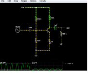
Circuits > Transistors > Common Emitter Amplifier
I changed the Beta to 35 from 100. Next I change the voltage to 9 V what is available.
I get a clipped sine wave and its in negative territory. What next?
Not sure if this goes in 'tools and software' but since I ma thinking of building a transistor amplifier
http://www.diyaudio.com/forums/solid-state/291017-build-low-power-transistor-amplifier.html
I need to undertand the concepts - and this simulator seems to fit the bill.
Circuit Simulator Applet
From the circutis menu, navigate to:
Circuits > Transistors > Common Emitter Amplifier
I changed the Beta to 35 from 100. Next I change the voltage to 9 V what is available.
I get a clipped sine wave and its in negative territory. What next?
beta = 35? Seems a bit low.
The problem is twofold:
1. The output RC highpass (5µ/1meg) has a loooong time constant, and this simulator allows swapping out component values on the fly. Put in 1µ + 100k instead, and you should see DC-centered output after a while. (I recommend swapping out the other 5µ as well.)
2. This common emitter amplifier has too much gain (~10x) to support 500 mVp / 1 Vpp input on +9 V (1 Vpp x 10 = ?). Even if you optimize the bias resistors by e.g. swapping out the 110k for a 75k, you'll still get rounded tops. Things look better at 300 mVp.
Have you already done a bit of reading yet? Simulators are handy for playing around once you have grasped a few basic concepts.
Gain
Beta for this transistor:
MPS2907. Data sheet gives
DC Current Gain
(IC = −0.1 mAdc, VCE = −10 Vdc)
(IC = −1.0 mAdc, VCE = −10 Vdc)
(IC = −10 mAdc, VCE = −10 Vdc)
(IC = −150 mAdc, VCE = −10 Vdc) (Note 1)
(IC = −500 mAdc, VCE = −10 Vdc) (Note 1)
75
100
100
100
50
I presume you mean the 5 uF capacitor and the 1Mega Ohm resistor on the right side of the diagram? OK. That did not do any harm, the output sine wave amplitude increased about threefold.
I simply do not understand this part - 500 mVp - millivolts ? p? In any case the AC input is set as 500Mv however for an actual input from a mini rca output such as from a phone or MP3 player how can I reduce the output?
I need to do more reading, but these electronics sites are confusing especially the circuit diagram with the infamous "ground". I really wold prefer if they showed two terminals.
beta = 35? Seems a bit low.
Beta for this transistor:
MPS2907. Data sheet gives
DC Current Gain
(IC = −0.1 mAdc, VCE = −10 Vdc)
(IC = −1.0 mAdc, VCE = −10 Vdc)
(IC = −10 mAdc, VCE = −10 Vdc)
(IC = −150 mAdc, VCE = −10 Vdc) (Note 1)
(IC = −500 mAdc, VCE = −10 Vdc) (Note 1)
75
100
100
100
50
The problem is twofold:
1. The output RC highpass (5µ/1meg) has a loooong time constant, and this simulator allows swapping out component values on the fly. Put in 1µ + 100k instead, and you should see DC-centered output after a while. (I recommend swapping out the other 5µ as well.)
I presume you mean the 5 uF capacitor and the 1Mega Ohm resistor on the right side of the diagram? OK. That did not do any harm, the output sine wave amplitude increased about threefold.
2. This common emitter amplifier has too much gain (~10x) to support 500 mVp / 1 Vpp input on +9 V (1 Vpp x 10 = ?). Even if you optimize the bias resistors by e.g. swapping out the 110k for a 75k, you'll still get rounded tops. Things look better at 300 mVp.
I simply do not understand this part - 500 mVp - millivolts ? p? In any case the AC input is set as 500Mv however for an actual input from a mini rca output such as from a phone or MP3 player how can I reduce the output?
I need to do more reading, but these electronics sites are confusing especially the circuit diagram with the infamous "ground". I really wold prefer if they showed two terminals.
Last edited:
For a sine wave:
Vp = peak voltage;
Vpp = peak-to-peak voltage;
Vrms = root mean square voltage;
Vrms = Vp/Sqr(2); that's what you will see if you measure with your DMM (AC).
Why do you call the ground "infamous"? Everything marked with the "ground" symbol is connected together - this is a common ground bus. On the large complicated schematic diagrams it's much easier to use the ground symbols than connecting all these points with a wire - it would be difficult to follow.
So, why only 35 then? This particular circuit (with bias network = 75k/10k) draws about half a mA of quiescent current, so for most of the voltage swing beta should be above 75 and generally closer to 100. Plus you may have noticed that these are given as minimum values, and the graph of typical beta at normal temperatures is well above 100 even at 0.1 mA Ic.Beta for this transistor:
MPS2907. Data sheet gives
DC Current Gain
(IC = −0.1 mAdc, VCE = −10 Vdc)
(IC = −1.0 mAdc, VCE = −10 Vdc)
(IC = −10 mAdc, VCE = −10 Vdc)
(IC = −150 mAdc, VCE = −10 Vdc) (Note 1)
(IC = −500 mAdc, VCE = −10 Vdc) (Note 1)
75
100
100
100
50
Be careful to avoid using transistors in areas of heavy beta droop, which is above about 200-400 mA in this case. This could lead to some nasty effects, not to mention that GBW (datasheet Fig. 10) is dropping like a rock and may be good for some nasty intermodulation distortion.
Are you sure it's not just the scaling that changed?I presume you mean the 5 uF capacitor and the 1Mega Ohm resistor on the right side of the diagram? OK. That did not do any harm, the output sine wave amplitude increased about threefold.
There are a few different ways of specifying AC amplitudes in periodic signals:I simply do not understand this part - 500 mVp - millivolts ? p?
peak-to-peak: The distance between the very minimum and maximum of the waveform. If the latter is described as f(t) = A sin(ωt), the peak-peak amplitude is 2 A. Peak-peak voltages are given in Vpp or Vp-p (using any SI prefixes you can think of).
peak: The difference between zero volts and maximum amplitude, assuming a symmetrical waveform. For our sine f(t) = A sin(ωt), the peak amplitude is A, exactly one half of peak-peak voltage. Peak voltages are given in Vp. I used this because it is what the voltage source in simulation is set up with.
RMS (root mean square): The time integral of the waveform. This is useful for power comparisons to DC. For our sine f(t) = A sin(ωt), the RMS amplitude is sqrt(2) A. RMS voltages are given in Vrms.
In systems of known (load) impedance, it is common to specify load power levels instead, so you might see mW or W into N ohms. dBs referred to known power levels are also commonly used, e.g. dBm (re: 1 mW) or dBf (re: 1 fW) in RF. The dBu you find in pro audio also derives from there originally (nowadays re: 775 mV, which happens to be 1 mW @ 600 ohms - but nobody uses 600 ohm inputs in PA any more).
Using the volume control on said device sounds too simple...?In any case the AC input is set as 500Mv however for an actual input from a mini rca output such as from a phone or MP3 player how can I reduce the output?
")
Otherwise, a voltage divider?
BTW, there is no such thing as a "mini RCA", you surely mean a 1/4" / 3.5 mm minijack.
You're actually in good company there (Bruno Putzeys claims to never have seen a one-terminal voltmeter either). "Ground" is a shortcut that makes for neat and tidy schematics, nothing more. It's a node that you declare Your Reference Potential. Now a physically extended node that keeps the same potential everywhere under any and all conditions does not exist, of course - finite conductivity and inductance have a say in that. Hence why in layout, considerable effort may be invested into getting the grounding right. Currents do, after all, flow in loops, and things may get ugly if large and distorted currents share the same paths with very small but critical ones.I need to do more reading, but these electronics sites are confusing especially the circuit diagram with the infamous "ground". I really wold prefer if they showed two terminals.
I do think you should look for a good electronics textbook.
OK
I must say you guys are an extremely helpful and patient bunch. Has it do do with working with lethal voltages?
Yes, the amplitude has changed.
Recommend a good electronics textbook - something on Kindle and less than $10? OR a website?
The second one in this list is nicely illustrated.
Electronic Circuits: The Definitive Guide to Circuit Boards, Testing Circuits and Electricity PrinciplesMar 19, 2016
by Wayne Charles
Make: Electronics: Learning Through Discovery 2nd Edition
by Charles Platt (Author)
https://www.amazon.com/Electronics-...n_feature_browse-bin:618073011&s=books&sr=1-4
I learned my electricity from this book, 1982 or so edition: so will download and review.
https://archive.org/details/AdvancedLevelPhysics
Last edited:
How about both? And zero cost?Recommend a good electronics textbook - something on Kindle and less than $10? OR a website?
Six free, open-source, electronics textbooks:
https://www.ibiblio.org/kuphaldt/electricCircuits/
A knowledgeable enthusiast's website, full of non-technical explanations of electronics and electricity concepts: FUNWITHTRANSISTORS.NET
-Gnobuddy
About the ground symbol:
As a beginner I find the earth symbol confusing. I believe any diagram should be clear and unambigous. To complete a circuit you need all the components connected, a simple earth symbol without knowing where it connects to, is confusing. Also, there is nothing about wire lengths or how they are to be routed so as not to cause interference.
The "AC Source" has a single connection to the base, there is no indication of where the other end goes, presumably to the earth.
This online app displays a proper two-terminal source:
Online Circuit Simulator with SPICE
About the ground symbol:
As a beginner I find the earth symbol confusing. I believe any diagram should be clear and unambigous. To complete a circuit you need all the components connected, a simple earth symbol without knowing where it connects to, is confusing. Also, there is nothing about wire lengths or how they are to be routed so as not to cause interference.
The "AC Source" has a single connection to the base, there is no indication of where the other end goes, presumably to the earth.
This online app displays a proper two-terminal source:
Online Circuit Simulator with SPICE
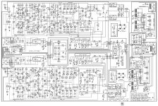
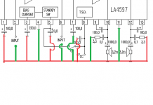
In fact, it's vice versa. Imagine, how many "unwanted" extra wires would be placed on the attached schematic, if the ground symbol would not be used.
The ground symbol makes the schematic more clean, more readable (picture 1).
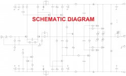
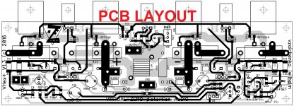
Schematic never gives you any information "about wire lengths or how they are to be routed so as not to cause interference" - these things are only visible on the layout (pictures 2 and 3).
Attachments
I remember the same thing, when I was a beginner. "Ground" or "earth" can be a confusing concept.As a beginner I find the earth symbol confusing.
There are applications where "earth" really IS used instead of a wire - and "earth" isn't even connected to earth. For example, almost every car is wired this way, with the metal body of the vehicle being used as "earth". You run a single wire from the battery positive to, say, a tail-light bulb; the other side of the bulb is "grounded" to the metal body nearby. There is no wire from the bulb back to the battery negative.
Since the tail-lights are easily 3 metres or more from the battery in most vehicles, you can imagine how much copper wire is saved by using this technique. Not to mention weight, complexity, et cetera.
As you get further into electronics, you'll probably find other confusing areas. It's a complex field, and there is a lot to understand. The physics behind the behaviour of an ordinary silicon diode, for instance, requires years of study to understand (calculus, statistics, quantum mechanics, etc), which is why most hobbyists never do understand it.
Layout is another entire area to master. Simple audio circuits aren't hard. But modern RF circuits are something else entirely. It takes a lot of expertise to do that well, and most of us don't have it.
-Gnobuddy
I find this diagram confusing, no doubt the data sheet will have the pin-outs so nothing to worry, but I can't get the connections from this diagram.
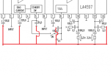
LA4597 power audio amplifier schematic
Gnobuddy you raise an important point, I am not sure, however what modern RF circuits are all about. Any examples? I had the impression that everything was either simplified using ICs or they were machine made like computer system boards. Is there an in between and what share of the market do they occupy? Just wondering.
LA4597 power audio amplifier schematic
Layout is another entire area to master. Simple audio circuits aren't hard. But modern RF circuits are something else entirely. It takes a lot of expertise to do that well, and most of us don't have it.
Gnobuddy you raise an important point, I am not sure, however what modern RF circuits are all about. Any examples? I had the impression that everything was either simplified using ICs or they were machine made like computer system boards. Is there an in between and what share of the market do they occupy? Just wondering.
I find this diagram confusing, no doubt the data sheet will have the pin-outs so nothing to worry, but I can't get the connections from this diagram.
LA4597 power audio amplifier schematic
Gnobuddy you raise an important point, I am not sure, however what modern RF circuits are all about. Any examples? I had the impression that everything was either simplified using ICs or they were machine made like computer system boards. Is there an in between and what share of the market do they occupy? Just wondering.
OK, let me try to explain.
The box in the middle is LA4597 IC. Its pin numbers are shown at the bottom side of the box (1 to 13). Don't pay attention to the drawing inside the box - it's gust showing the IC's internal principal arrangement (2 channels, standby circuit, etc.).
All the wires, ending with perpendicular line, are the ground symbols (example - the ground, connected to pins 4 and 11). All these symbols are connected with a common wire, going to the common terminal of the power supply - in this particular case, to "-" terminal of 9V or, say, 12V DC power supply.
Pins 2 and 6 are the inputs of channel 1 and channel 2 - they go the the "hot" pins of each input terminal. The "cold" pin of each input terminal is connected to the same common "ground" wire, where all the ground symbols are connected.
+Vcc is where the "+" terminal of the power supply is connected.
Speaker terminals are connected:
- "hot" pin goes to the negative pin of 1000.0 uF capacitor.
- "cold" pin goes to the common "ground" wire again.
All capacitor values are shown in uF (micro-farads), all resistor values are shown in ohms.
What else? Looks like that's it. This is a low power, rather low quality, but very simple stereo amplifier.
With regards to "machine made like computer system boards" - even though in the digital world automated PCB routing is used successfully, even there there is a lot of manual work.
In high-performance analog audio designs we use manual routing most of the time, as there are no automated routers, able to take in account all the factors, preserving the quality.
With the relatively high-power amplifiers, say, 50W and above, situation is even more complicated, as rather high currents are involved in the output stages, so traces must be shorter and wider than normal. We never rely on automatic routers in this case.
Hope this helps
Cheers,
Valery
Yes it helps. I have drawn the ground wire connecting the various wires ending in ground, and it is 100% clearer to me. Maybe it wastes ink, but as a user interface, as recommended in the computer software industry, this one is better, I think.
One thing that bothers me is connecting any side of the input signal or output signal to the same 'earth' that the power supply is connected to - doesn't the DC current affect the line in and out electronics like speakers and source components? I am sure the answer is obvious, but clearing up this little point will help me.
For example in the circuit simulator at http://www.falstad.com/circuit/ the current is shown fluctuating at the earth terminals and the out terminals (first post).
If you look at the worldwide product categories for electronics, the most growth is in mobile devices, however, aduio-visual products and home appliances as well as econ-friendly, health care and security products seem to be areas where the large hand-assembled boards will dominate, but I may be wrong.
Electronics Market Spurred by Technology and Wearable Items: the Spring 2015 Hong Kong Electronics Fair Survey | HKTDC
Any high powered HiFi amplifier will then have the hand-assembled boards? What about this one?
Attachments
Last edited:
Yes it helps. I have drawn the ground wire connecting the various wires ending in ground, and it is 100% clearer to me. Maybe it wastes ink, but as a user interface, as recommended in the computer software industry, this one is better, I think.
One thing that bothers me is connecting any side of the input signal or output signal to the same 'earth' that the power supply is connected to - doesn't the DC current affect the line in and out electronics like speakers and source components? I am sure the answer is obvious, but clearing up this little point will help me.
For example in the circuit simulator at Circuit Simulator Applet the current is shown fluctuating at the earth terminals and the out terminals (first post).
If you look at the worldwide product categories for electronics, the most growth is in mobile devices, however, aduio-visual products and home appliances as well as econ-friendly, health care and security products seem to be areas where the large hand-assembled boards will dominate, but I may be wrong.
Electronics Market Spurred by Technology and Wearable Items: the Spring 2015 Hong Kong Electronics Fair Survey | HKTDC
Any high powered HiFi amplifier will then have the hand-assembled boards? What about this one?
You have left a few "grounds" unconnected - see my green additions. Just want to stress this point again - as soon as you get some experience reading the schematics, your mind will adapt to the "ground" concept and it will be really easier to understand the topology with the ground signs, than with all of them connected with a wire on the schematic. Believe me, I went through this experience... some 40 years ago
Common ground is no problem, if it's arranged the right way inside the amplifier. There are some more complicated setups, like "lifted ground" for the inputs, allowing ground loops elimination, especially useful in multi-channel arrangements, or even completely insulated balanced inputs (3 wires), most popular in professional equipment - pre-amps, mixers, stage amplifiers - dealing with long interconnects and electrically "noisy" environments.
However, in many home audio systems, most likely, all the ground wires of all the devices will be connected to each other.
The boards... ok, we have to distinguish the manual routing (when we design the layout) and manual assembly (when we actually assemble and solder the board).
Assembly and soldering are automated in most cases (unless it's a DIY hand-made build). Even expensive equipment manufacturers, producing hand-crafted devices, use automated soldering - it's just a very mature high-quality technology.
Coming back to manual routing - yes, most of high-quality audio equipment BCBs are designed with manual routing. Well, PCB design software is used anyway, but engineers place the parts on the boards and route the traces manually. That's the way to ensure the quality. I personally, after gaining some experience in PCB design, use automated routing for digital boards only.
Attachments
I see the ones I did not connect. OK.
Just have to try one amplifier circuit and see...
Yep!

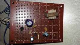
Transistor radio I built
Here in image of the remains of a breadboard transistor radio I built in 1993. It worked, I recall, however I was disappointed that it needed a 9V battery and I did not have a proper case for it.
I cannot recall the quality of the sound, but then I never imagined I could connect it to anything more than 2 inch speakers.
I am going to de-solder all the parts and try out a simple amplifier circuit.
Attachments
I am not qualified to answer the question. However, Tubelab (George) on this forum designed RF boards for cellphones for many years, and he is also very good at explaining things. Why not ping him and ask if he is willing to share some of his amazing store of knowledge here?Gnobuddy you raise an important point, I am not sure, however what modern RF circuits are all about. Any examples?
-Gnobuddy
- Status
- This old topic is closed. If you want to reopen this topic, contact a moderator using the "Report Post" button.
- Home
- Amplifiers
- Solid State
- Understanding Transistor amplifier with an online simulation