If legs are oxidised, you should rmove them, then scratch the legs with a knife, or what ever that gets rid of the oxidisation, then tint it. Theres another way which I think is adding flux before tinting it
If those emitter resitors are not wire rounds, they could have aged and gone bad, so you might want to check that out
Emitter resistor legs could be oxidized perhaps.
If those emitter resitors are not wire rounds, they could have aged and gone bad, so you might want to check that out
If legs are oxidised, you should rmove them, then scratch the legs with a knife, or what ever that gets rid of the oxidisation, then tint it.
Yes I know, but the emitter resistors are well wrapped in insulation. What I did is I pierced a hole there. I posted a pic earlier, you see? I can't see the actual legs, just get the feel of them with multimeter lead tip. It was only suggestion, since the other channel measures easily.
DC offset is determined at the input stage of the amplifier, not the output stage and there is no means of adjusting it here. You could swap resistors around the LTP (IC101, 102) but these are dual transistors, very difficult to ensure genuine replacements for, so this would need great care. Don't mess with those 2SA733 duals unless you know what you are doing: Sansui G-301 - Manual - AM/FM Stereo Receiver - HiFi Engine
Your multimeter may not be able to measure less than 1 decimal point on the resistance scale so would round up the 0.4R.
Well I better not to mess around with those duals. They are 2SA798 according to schema. Anyway there's an idea, I could measure those resistors again and determine if one of them seem out of spec in circuit. Amp sounds pretty nice now, but if there are means to bring down the dc offset with simple steps I would certainly like to see the offset going down.
That's what I think also, it rounded up to 0.4R. Indicates the emitter resistors could be alright.
Thanks for the input guys.
Well, you have to use a trim pot to tune the dc voltage, If you skim through the manual you may find something with reguards to that.
Yeah I had skimed through that pictureYes I know, but the emitter resistors are well wrapped in insulation. What I did is I pierced a hole there. I posted a pic earlier, you see? I can't see the actual legs, just get the feel of them with multimeter lead tip. It was only suggestion, since the other channel measures easily.
DC offset is determined at the input stage of the amplifier, not the output stage and there is no means of adjusting it here. You could swap resistors around the LTP (IC101, 102).
Now I had time to focus on this again.
So, I measured all resistors around IC101 and 102. Cross referencing them between channels indicates they're all the same. Also measured readings from IC101 and 102 in circuit. Resistance readings almost matches to each other in circuit. Also all of the resistors just before the output transistors indicate they're good.
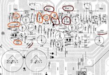
The major cause were the blown output transistors TR16, 17 and transistors TR12, 13 (shown in dark red).
Just for a thought; would it be a good idea to replace all of the small ceramic capacitors (circled in orange) on the left channel? Just thinking, if the damaged transistors passed on high voltage that damaged ceramic caps.
Also the resistors R67, 68 were gone bad, tho now replaced, but if this resulted damage to components further down the circuit?

Now DC offset on right channel is 0mv and on the left it's about 43-44mv after the unit's been on for an hour.
Tested the headphones jack and unfortunately I can't hear any output. Could this issue play a part here?
Anyway, any thoughts are appreciated.
Attachments
Last edited:
No need to replace ceramic or film caps unless you have had a large power surge like a lightning strike. However, you now say that you now have no headphone output at all? Yet you still have speaker output? You would have a wiring/socket problem if that's the case.
If you are just looking at nominal and marked values on the resistors, I think you misunderstand how the input stage works. The imbalance is in the transistors within the IC itself, not the external parts so if you want to shift the current sharing balance and thus null the voltage offset better, you have to force it by changing the collector resistors quite a lot or inserting a small value resistor in either emitter leg - perhaps only a few ohms. Test and see if you can without touching the IC soldering unnecessarily.
This is not a simple fix and you need to take care with testing which side needs the resistance added and how much. I don't recommend anyone do this but if you must have balance, you need to understand how it is established by the LTP input stage. Normally, with a discrete transistor pair, we just match transistors for the best figures but here you can't, so you need to force the current in favour of the appropriate transistor.
I suspect though, your present problems with unstable operation may be due to a faulty LTP anyway, so keep a eye on the stability of each output offset voltage - so far it suggests at least one amplifier has a faulty LTP IC.
No need to replace ceramic or film caps unless you have had a large power surge like a lightning strike.
Ok, I see. I found this thread by googling diyaudio threads. Suggests ceramic caps may degrade over time.
http://www.diyaudio.com/forums/solid-state/238348-would-old-electrolytic-caps-cause-dc-offset.html
However, you now say that you now have no headphone output at all? Yet you still have speaker output? You would have a wiring/socket problem if that's the case.
True. I tested the socket and no output, nothing. Tested the headphones with another source and headphones work. Tried to scrape the contacts with small screwdriver with no luck. Maybe I should use lubricating agent?
If you are just looking at nominal and marked values on the resistors, I think you misunderstand how the input stage works. The imbalance is in the transistors within the IC itself, not the external parts so if you want to shift the current sharing balance and thus null the voltage offset better, you have to force it by changing the collector resistors quite a lot or inserting a small value resistor in either emitter leg - perhaps only a few ohms. Test and see if you can without touching the IC soldering unnecessarily.
I suspect though, your present problems with unstable operation may be due to a faulty LTP anyway, so keep a eye on the stability of each output offset voltage - so far it suggests at least one amplifier has a faulty LTP IC.
Yea, just tested the IC if it shows totally erratic behaviour, but obviously I can tell if it's working or if it's totally gone bad. Not to say anything about balance.
Like Welcome said earlier the channel is in the top end of alright, so I better not to mess around with that IC. If it slips when power on, it could be gone for good and other parts too. Thanks for the input.
OK, other problems aside, the headphones are wired via 220R resistors R81,82 directly to the power amplifier outputs. The outputs then connect to the rotor of the speaker selector switch and so to the selected speakers. So there must be a breakdown there - perhaps soldering or connections weren't remade when the output transistors were replaced? These are mechanical switch sockets and I would expect the action of inserting the headphone plug a few times would clean the contacts sufficiently to work or at least crackle a bit if there was a poor contact.
There's still problem(s) present.
Maybe it's the IC or then it's not
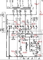
Take a look at the voltages at the power supply area I measured from the circuit (pic attached).
I should have 15V from blue rail (?), but it's only 9.2V at the F01 (fuse holder ends) and I noticed if I turn the AC plug other way around to the AC wall socket I have 8,1V only present at the same location. I have 23V at the end of F02 and F03. Other voltages down the circuit have only minor change, like few decimals or so no matter which way the AC plug is.
The unit seems to work still alright, sound is pretty good. I wonder it could be even better if the voltages were correct.
Lubricated the voltage selector well, no change.
Headphones provide no output, I have inserted the plug multiple times. It's mute.
Could it be a broken diode?
Maybe it's the IC or then it's not
Take a look at the voltages at the power supply area I measured from the circuit (pic attached).
I should have 15V from blue rail (?), but it's only 9.2V at the F01 (fuse holder ends) and I noticed if I turn the AC plug other way around to the AC wall socket I have 8,1V only present at the same location. I have 23V at the end of F02 and F03. Other voltages down the circuit have only minor change, like few decimals or so no matter which way the AC plug is.
The unit seems to work still alright, sound is pretty good. I wonder it could be even better if the voltages were correct.
Lubricated the voltage selector well, no change.
Headphones provide no output, I have inserted the plug multiple times. It's mute.
Could it be a broken diode?
Attachments
The AC voltage at F01 should be 15V measured with respect to the other end of that secondary winding (at connection point 14 or 20). You may be reading only about half the rectified DC voltage if you measure 9V with respect to ground. As the actual rectified DC output of that supply is 19V, I don't think you have the right corresponding AC test point or your meter is set to DC.
There isn't much load (no voltage drop across R91) so there can't be many problems there. However, you may need to replace C40, C50 or possibly one of the rectifier diodes D07,08,09 or 10 if they have failed, as you suspect. Those diodes usually fail shorted but occasionally open - easy to check anyway. BTW, are both lamps working and to check the transformer again, what is the voltage across connections 18,20?
There isn't much load (no voltage drop across R91) so there can't be many problems there. However, you may need to replace C40, C50 or possibly one of the rectifier diodes D07,08,09 or 10 if they have failed, as you suspect. Those diodes usually fail shorted but occasionally open - easy to check anyway. BTW, are both lamps working and to check the transformer again, what is the voltage across connections 18,20?
You were right. I messed up the measurement on F01 transformer output. It's 15.31 VAC across 18 and 20. Bulbs are new and working, but they're only 6V, since the electronics shop didn't have 8V in stock.
Measurements are in VDC with no input signal and input selector to Phono.
Without speakers connected.
Anyway, I'm confused how to measure diodes correct?
I have 7.4 VDC or VAC over D07,08,09,10 even if I reverse the leads. Is this anywhere near where it should be? There should be a drop in the other way I think.
According to schema I should have 22.5V at 21, but I have only 19.2-19.4Vdc there. If I switch the input selector to FM, reading drops to ~17.4Vdc.
All electrolytic caps were replaced on the power supply except the 2x 100uF caps, which I popped out for a test, tested good and put them back.
You probably have another shorted transistor (or diode) somewhere. Something's pulling down the voltages. It is common for other parts (other than the output transistors) to fail when an amp dies. You have to test every single semiconductor (preferably out of circuit) on the bad channel. I would focus on the small parts first, they can commonly be shorted but still allow the amp to sort of work.
Yea, that's what I'm afraid of.
It will be a b*tch to find!
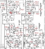
Here are voltages from the preamp and output stages. Pic attached. I don't know whether it's any help to resolve the issue.
Measured in VDC. No input signal.
I think the voltages starts going wrong at the junction of R15 and R19.
C09 and C10 BP are among the few I didn't replace on the board, because there were no stock for them. Should I pull them out again and re-check or do you think this part of the board is not necessarily culprit for incorrect voltages?
It will be a b*tch to find!
Here are voltages from the preamp and output stages. Pic attached. I don't know whether it's any help to resolve the issue.
Measured in VDC. No input signal.
I think the voltages starts going wrong at the junction of R15 and R19.
C09 and C10 BP are among the few I didn't replace on the board, because there were no stock for them. Should I pull them out again and re-check or do you think this part of the board is not necessarily culprit for incorrect voltages?
Attachments
Oh you have the infamous 2SA798 double transistor in there. Not saying they are the cause of the fault, but these are VERY bad transistors that very commonly cause various problems. I would definitely replace them with two matched KSA992 transistors for each channel. B C E C B is the pinout, so you will have to solder the emitter legs of the two transistors together to form a new pair. I always replace these whenever I see them, and super glue the two KSA992 with the flat ends together. It's a great solution.
Last edited:
The silicon diodes in a bridge rectifier are easiest to measure out of circuit. They will have a DC forward voltage drop of 0.7V but this is confused by the anti-phase current in the other diodes. It's difficult with just a multimeter. In any case, its not hard to Google what you want know. You can verify what I am saying here, for example: In-Circuit Testing of Diodes and Rectifiers....Anyway, I'm confused how to measure diodes correct?
I have 7.4 VDC or VAC over D07,08,09,10 even if I reverse the leads. Is this anywhere near where it should be? There should be a drop in the other way I think.....
Your 6V globes wont last very long with a 15V supply. Perhaps a 2W series resistor of 22R would help there.
As I pointed out, there is nothing pulling the voltage down since there is no voltage drop across R91. You could expect a drop when the tuner is powered though.
Your 6V globes wont last very long with a 15V supply. Perhaps a 2W series resistor of 22R would help there.
As I pointed out, there is nothing pulling the voltage down since there is no voltage drop across R91. You could expect a drop when the tuner is powered though.
Why manufacturer put 8V bulbs there? According to schema correct bulbs are 8V. I know 6V won't last so long, but it's not a big problem to replace them.
According to schema I should have 22,5V at pin 21. There I have just 19,4VDC and with tuner on, speakers connected and decent volume I get 17,1VDC reading. This is "pulling down the voltages" issue. Sorry, if I didn't make myself clear enough. So I have at least 3,1VDC missing somewhere.
As today I started to measure voltages once again I slipped the multimeter probe between D07,08 I think... *zap* power went out. I was very lucky, only F01 fuse blown. I replaced F01 with 1A and luckily everything works as before (carried out some tests before to make sure readings look about normal). No damage done, but I can't afford these mistakes.
I would focus on the small parts first, they can commonly be shorted but still allow the amp to sort of work.
Do you mean by "small parts" semiconductors only? I mean the major damage on this amp was near the output transistors including multiple fried resistors. I'd just like to think the problem lies there. I've been wondering, if it makes any difference to try and replace those small ceramic caps near output transistors?
Thanks for the tip on double transistor. Sounds like a patent job. Looks like this IC could be the culprit, if you have to take one guess.
Is a big power surge comparable to shorted output transistors?
Next step I need to check the availability on these components.
You haven't checked the diodes yet so let's not jump to conclusions. The 3.1V you refer to is being lost in the power supply before R91. That much is clear and it means the problem is within the few parts shown on the schematic to the left side of the resistor. Check how much current is drawn from the transformer first, if you want to get answers to where the voltage is dropped.
There are several ways of using multimeter leads safely:
First, don't use probes on hard surfaces where they will slip, particularly if they don't have sharp points. Buy some short leads with crocodile clips on both ends or use leads terminated with mini hooks, IC clips etc. You can buy suitable leads cheaply if wish but if you plan to play with more old equipment, get good quality test equipment and learn to use it.
You haven't checked the diodes yet so let's not jump to conclusions. The 3.1V you refer to is being lost in the power supply before R91. That much is clear and it means the problem is within the few parts shown on the schematic to the left side of the resistor.
I like the sound of that. Problem lies within few parts

So now it's done.
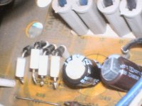
With diode mode and one leg desoldered from the board (pic).
D07
Forward: 0.534V
Reversed: OL
Resistance forward 6.95M ohm
D08
Forward: 0.540V
Reversed: OL
Resistance forward 8.32M ohm
D09
Forward: 0.535V
Reversed: OL
Resistance forward 6.58M ohm
D10
Forward: 0.555V
Reversed: OL
Resistance forward 11.0M ohm
According to guide. Good forward bias is between 0.5V and 0.8V.
These should all be okay then?
D10 showing slightly higher reading compared to other 3.
What you think could this explain difference in voltage?
Attachments
Good work so far. Note though, the particular diode measurements will depend on the battery condition and design of your multimeter. These are not the best instrument for precise semiconductor measurements but good enough for the job of telling us that the diodes are still functional.
At their full rated forward current of 1A, similar diodes like 1N4001-7 will actually drop 1.1V , a lot more than 0.5V at typically only 5uA, when measured with a multimeter. So you can see that Vf is quite a rubbery number and not a fixed potential at all. http://www.vishay.com/docs/88503/1n4001.pdf
If you accept that a good diode measures between 0.5 and 0.8V on a multimeter, don't be too concerned about a measurement range of only 0.535-0.555V. That's a range of just 3.7% and within the likely accuracy limits anyway.
The next step is to resolder the diodes, then temporarily remove the lamps and recheck the voltage. I suspect they have a higher current rating than the originals but I have no idea what the 15V transformer winding current rating is.
Last edited:
There's engraving on the side of the bulbs: 6V 0.1A.
Under the F01 fuseholder (1A), there's a sticker with printed text: 800mAt
Yea, looks like the diodes are alright by the readings.
And yes, battery life is relevant here.
On the multimeter manual I have following:
- Diode tester test current (typical) 0.25 mA
- Diode tester open circuit voltage 1.6 V dc
Bulbs are new, they have maybe 10 hrs behind only.
Wouldn't this information rule out the possible problem regarding the bulbs?
Should I still proceed with the test?
- Status
- This old topic is closed. If you want to reopen this topic, contact a moderator using the "Report Post" button.
- Home
- Amplifiers
- Solid State
- Vintage Sansui restoration