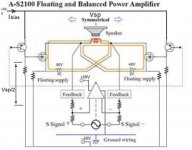
If you extend the picture from entry#1 (think NPN not MOS) it is clear that the floating doesn't exit.The powersection is related to the minus rail of the driver section.
The output is sort of concertina, half of the output on the emitter, other half on the collector.The gain is 2x total.
Mona
The output is sort of concertina, half of the output on the emitter, other half on the collector.The gain is 2x total.
Mona
Attachments
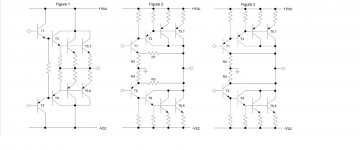
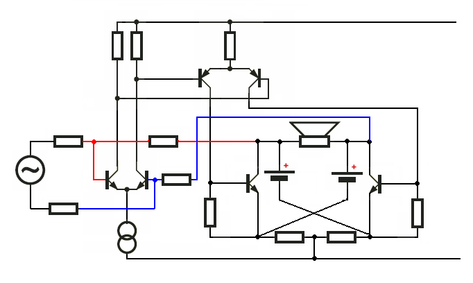
In the picture below Figure 1 represents a classic triple emitter-follower output stage; Figure 2 represents an earlier Bryston output stage which, for a commercial design, best resembles (w/o floating ground) that of the Yamaha AS1000, except for the pre-driver transistors T1 and T2 which are the only ones configured as a common-emitter voltage amplifier, with the driver and output transistors being connected as cascaded emitter-followers, so it could be described as a CE-EF-EF; and finally Figure 3 intends to show what the Yamaha AS1000 output stage would look like whithout the floating ground arrangement (I invented this one for illustration purposes, as I've never seen such an arrangement), clearly here we are in the presence of another, albeit different, triple-EF output stage.
My question is, does the output stage of Figure 3 make sense? Isn't that the output stage of the Yamaha AS1000 amplifier applied to the floating ground concept?
Last but not least, what would be the difference between the output stages of Figure 1 and 3, performace wise? (provided that 3 makes sense)
Attachments
Last edited:
... common-emitter output transistors in a push-pull configuration. Is this correct?...
Yes.
Best wishes
David
In push-pull topologies (complementary, quasi-complementary and circlotron), the output load is said to be referred to ground, while in a single-ended topology it is connected to ground.
In order to avoid a huge saturation of the predriver, bipolar output transistors need to be configured as emitter / source followers, driven by a common-collector / source amplifier. By contrast, a single FET output transistor can be driven by a more forceful and high frequency, resistor loaded common-emitter voltage amplifier. Regarding performance, figure 1 and 2-3 are similar.
Push-pull topologies are inherently unstable, bipolar transistors are inherently nonlinear and large current stages inherently suffer from a low frequency range (poor high frequency performance) aggravating instability. I would try to use just one common-collector predriver and stick with circlotron.
Yes.
Best wishes
David
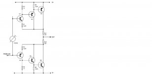
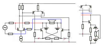
But David, Douglas Self in his «Audio power amplifier design handbook» clearly states, regarding the circuit in the figure below:
"The output stage (...) is another variation on the triple output."
"It could be written as a [CE – EF – EF] triple output stage."
" (...) has common-emitter pre-driver, with both the driver and output transistors connected as emitter-followers"
If one forgets about the floating ground, it is almost the same topology as the one of the Yamaha as1000, in that the output transistors are arranged in the same way, as emitter-followers, right?
I can't see the difference (except for the pre-driver)...
Attachments
Last edited:
In push-pull topologies (complementary, quasi-complementary and circlotron), the output load is said to be referred to ground, while in a single-ended topology it is connected to ground.
In order to avoid a huge saturation of the predriver, bipolar output transistors need to be configured as emitter / source followers, driven by a common-collector / source amplifier. By contrast, a single FET output transistor can be driven by a more forceful and high frequency, resistor loaded common-emitter voltage amplifier. Regarding performance, figure 1 and 2-3 are similar.
Push-pull topologies are inherently unstable, bipolar transistors are inherently nonlinear and large current stages inherently suffer from a low frequency range (poor high frequency performance) aggravating instability. I would try to use just one common-collector predriver and stick with circlotron.
The risk of instability shouldn't surpass what is gained in terms of speaker control.
I am yet to discover a better output stage to accurately control a speaker than a well designed triple emmiter-follower output stage with bipolars.
Last edited:
OK, it would be more accurate to say that in push-pull topologies, the output is referred to ground and the output load is balanced to ground. This is a feature of all push-pull topologies (complementary, quasi-complementary and circlotron).
Also instability is a feature of all push-pull topologies (complementary, quasi-complementary and circlotron).
You can implement the triple emitter-follower constellation of your choice in the circlotron topology without losing its speaker control capability.
Also instability is a feature of all push-pull topologies (complementary, quasi-complementary and circlotron).
You can implement the triple emitter-follower constellation of your choice in the circlotron topology without losing its speaker control capability.
You can implement the triple emitter-follower constellation of your choice in the circlotron topology without losing its speaker control capability.
Precisely! Thank you N101N!
")
So, do we agree that the Yamaha as1000 (and the as2000 for that matter) does have a triple emitter-follower output stage implemented in a circlotron topology?
Yes we do. A configuration transferred from a complementary push-pull topology retains its main characterististics in the circlotron topology. Was this your actual query?
Basically, yes!
However, I would recommend an interesting test: try to compare a Yamaha as1000/2000 to the newer as1100/2100, preferably using the MAIN IN input, which bypasses the preamp stage (volume, balance and tone controls), knowing that the newer versions have dropped the pre-driver transistor and replaced the output bipolars for mosfets... then you can assess what is merit of the circlotron topology and what it is not (as both versions, old and newer, implement this topology).
Was this your actual query?
Actually, my original query intended to know if the output stage of the Yamaha as1000 is a triple emitter-follower, regardeless of the circlotron topology.
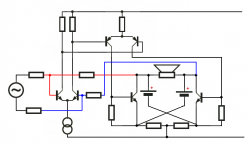
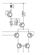
From what I see the A-S1000 topology looks something like this:
Very nice drawing, thank you Jony!
I think you stand correct, except for the input LTP which is comprised of two input J-FETs in the Yamaha AS1000.
With 3 x 2SC4468 in parallel (six per channel) as output transistors and as a driver, they use two emitter followers in cascade (2SC2705 and 2SC5291).
Which makes it a triple emitter-follower output stage: 1) three output transistors in parallel - 3 x 2SC4468 - that ideally would act as a single "bigger" one; 2) one driver - 2SC5291 and 3) one pre-driver - 2SC2705. Wouldn't you agree?
Last edited:
There is a connection to the negative rail to pull the driver output down.
Mona
Thank you Mona for the correction!

what is amazing is that the second differential has a CSS in place of the first
It looks like they use this current source to set the output stage quiescent current. Also, they are using a diode connected BJT (Q103) and mounted it on the heatsink to prevent the thermal runaway. And this diode connected BJT's is a part of this current source.
Attachments
- Home
- Amplifiers
- Solid State
- Yamaha's new floating and balanced power amplifier