Self...clearly states..."It could be written as a [CE – EF – EF] triple output"
That is a mistake, it's in my 5th edition, I don't know if it's been fixed for the 6th.
Of course, you may suspect that it's more likely that an almost anonymous internet commentator is mistaken rather than a well known author.
So check it yourself, Edward Cherry analysed this in a Wireless World article.
The article is available at Keith Snook's website, or use the library.
Jony's redraw shows quite clearly that the speaker is driven by the collectors of the OPS.
Best wishes
David
Last edited:
Jony's redraw shows quite clearly that the speaker is driven by the collectors of the OPS.
There may be more subtlety here than I initially realized, the Yamaha circuit seems a bit more complicated than the usual floated power supply CE OPS.
The speaker is also driven by the emitter of the OPS via the floated power supply.
I don't think my earlier statements are incorrect but I will have to check this, thanks for the puzzle.
Best wishes
David
Last edited:
what is amazing is that the second differential has a CSS in place of the first
Oups surprising, not amasing.
this is the first time I do not see a css on the input of a recent amp.
Thanks Jony, i did ont see the mounting on heatsink
That is a mistake, it's in my 5th edition, I don't know if it's been fixed for the 6th.
It is not a mistake, even if the the present transistor operation cannot be entirely described by the classification. What would your designation be?
Jony's redraw shows quite clearly that the speaker is driven by the collectors of the OPS.
The speaker is also driven by the emitter of the OPS via the floated power supply.
It would be extremely odd if the speaker was not be driven by the collector-emitter junctions. Taking just one terminal into account is nonsensical.
There may be more subtlety here than I initially realized, the Yamaha circuit seems a bit more complicated than the usual floated power supply CE OPS.
The mode of operation is necessarily the same in all topologies, however, the transfer characterisics of push-pull topology differ from the transfer characterisics of single-ended topology.
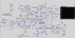
Yamaha floating and balanced power amplifier LTspice simulation
Reference Yamaha A-S1000 , A-S2000 & A-S3000 service manual , simplify the power amp schematic.
Success running simulation , work well 40V-peak 100W/8R.
Gain 15x
FFT THD
in=0.27v out=4v(9dB) 1w/8R THD 2nd -99(-108)dB 3rd -76(-85)dB
in=2.7v out=40v(29dB) 100w/8R THD 2nd -92(-121)dB , 3rd -74(-103)dB

Reference Yamaha A-S1000 , A-S2000 & A-S3000 service manual , simplify the power amp schematic.
Success running simulation , work well 40V-peak 100W/8R.
Gain 15x
FFT THD
in=0.27v out=4v(9dB) 1w/8R THD 2nd -99(-108)dB 3rd -76(-85)dB
in=2.7v out=40v(29dB) 100w/8R THD 2nd -92(-121)dB , 3rd -74(-103)dB
Attachments

- Home
- Amplifiers
- Solid State
- Yamaha's new floating and balanced power amplifier